Because injection locations greatly influence the way in which the plastic flows into the mold cavity, their postioning directly affects part quality.
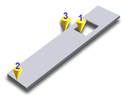
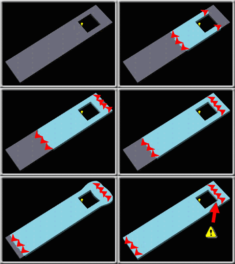
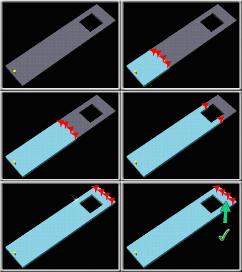
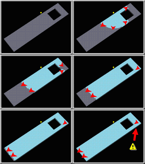
One of the goals when selecting polymer injection locations is to ensure that all flow paths in the cavity fill at the same time. This prevents overpacking along the flow paths which might otherwise fill first. The three possible polymer injection locations in the following diagram of a model show how the polymer injection location can be used to help balance flow.

| 1 | 2 | 3 |

|

|

|
The polymer injection location can also be used to change the position of weld lines and air traps, and reduce hesitation and other molding problems. The above animation shows how polymer injection locations 1 and 2 cause a weld line to form on the right of the model, and polymer injection location 3 causes a weld line to form on the bottom right of the model. In some cases it is necessary to have more than one polymer injection location. Other methods can be used to help balance flow paths, such as including flow leaders or flow deflectors.