Gates can have many different configurations but they are broadly classified according to their method of degating into manually trimmed and automatically trimmed gates. Special features are incorporated into automatically trimmed gates so that the gates are trimmed or sheared when the mold opens and the parts are ejected.
Automatically trimmed gates are used to avoid gate removal as a secondary operation, and to minimize gate scars
- Hot-runner or hot-probe gate
- Pin gate
- Submarine, tunnel, or chisel gate
- Valve gate
- Hot-runner or hot-probe gate
-
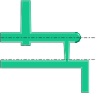
A hot-runner gate, which is shown in the following diagram, is generally used to deliver hot material through heated runners directly into the cavity to produce runnerless moldings.

The gate or gate tip can have many different configurations from full round to annular. The geometry and size of the gate tip will determine how the gate freezes and the gate scar formed.
- Pin gate
-
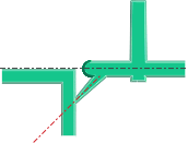
The pin gate is used in a three-plate mold design, where the runner system is on a secondary mold parting line and the part cavity is in the primary parting line. Reverse taper runners drop through the middle plate, parallel to the direction of the mold opening as shown in the following diagram.

As the mold cavity parting line is opened, the small-diameter pin gate is torn from the part. A secondary opening of the runner parting line ejects the runners. Alternatively, the runner parting line opens first. An auxiliary, top-half ejector system extracts the runners from the reverse taper drops, tearing the runners from the parts.
Dimensions:
Typical gate sizes are 0.2 to 1.5 mm in diameter. The design is particularly useful when multiple gates per part are needed to assure symmetric filling, or where long flow paths must be reduced to assure packing to all areas of the part.
- Submarine, tunnel, or chisel gate
-
A submarine gate is used in two-plate mold construction. An angled, tapered tunnel is machined from the end of the runner to the cavity, just below the parting line, as shown in the following diagram.

As the parts and runners are ejected, the gate is sheared at the part.
If a large diameter pin is added to a non-functional area of the part, the submarine gate can be built into the pin, avoiding the need of a vertical surface for the gate. If the pin is on a surface that is hidden, it does not have to be removed.
Multiple submarine gates into the interior walls of cylindrical parts can replace a diaphragm gate and allow automatic degating. The out-of-round characteristics are not as good as those from a diaphragm gate, but are often acceptable.
Dimensions:
The typical orifice diameter of the gate is 30 to 75 percent of the part wall thickness. The gate is tapered at a minimum of 10 degrees per side to ensure proper ejection. It is common to have the gate taper to the diameter of the runner.
- Valve gate
-
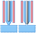
The valve gate adds a valve pin to the hot runner gate. Valve gates have a larger gate diameter and they can be opened and closed as needed as shown in the following diagram. This smooths over the gate scar.

Since the packing cycle is controlled by the valve pin, better control of the packing cycle is maintained with more consistent quality.