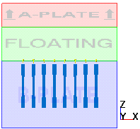
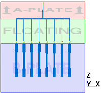
Creating injection system for a 3-plate mold

The runner modeling functionality always assumes that the parting plane corresponds to the global XY plane. The sprue and drops are then created perpendicular to this parting plane. In the case of a 3-plate mold however, to create a runner system with the correct orientation you need to use a parting plane (XY plane) that is parallel to the actual mold parting plane. The drop runners will be created at right angles to this plane. The required procedure is described below.
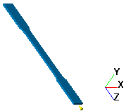
  1. Display the cavity.
  2. Pick the injection location.
  3. Align the cavity.

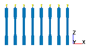
    The mold parting plane will lie in the XY-plane. Make sure that the injection location is on the positive z-direction side.


  4. Copy the cavity (in a linear arrangement) as many times as you need. The cavities should be in a row in the x-direction.

  5. Position the parting plane just above the cavities. The distance between each injection location and the parting plane will become the gate length.
  6. Click the Specify Mold Dimensions button.
  7. Select the Floating Plate check box.
  8. Enter thicknesses for the floating plate and the A plate. The floating plate thickness will become the length of the runner drops. The A plate thickness will become the sprue length.

  9. Set the runner system defaults.
  10. Position the sprue and generate the gates.
  11. Create a drop runner from each gate up to the plane between the floating and A plates.
    1. Click the Create Runners button.
    2. Click on a gate.
    3. Click Mold and click OK.

      A drop appears between the gate and the plane between the floating and A plates.

    4. Right-click on the display to close the dialog.
    Repeat steps a-d for each of the gates.
  12. Connect the drops to the sprue with a single horizontal runner. The mold is now ready for analysis.