The positioning of injection locations greatly affects material orientation and part warpage.
In some cases, changing the gate position is the only way of controlling the orientation effects and producing a satisfactory design.
Each polymer injection location injects the material under the same pressure. Unless an end-of-fill spike occurs, the pressure increase during the injection period is generally linear. The aim of proper gating is to avoid problems associated with overpacking, such as variation in shrinkage and product sticking in the cavity.
Design Rules
- Gate centrally to provide equal flow length
-
Centralized gates provide equal flow lengths to all extremities of the part. This results in more even packing in all directions and a lower shrinkage difference, which leads to a higher quality part and lower rejection rate.
- Gate symmetrically to avoid warpage
-
Symmetrical parts should be gated symmetrically to achieve balanced flow and avoid differential shrinkage and subsequent warpage of the part.
- Gate into thicker sections for better filling and packing
-
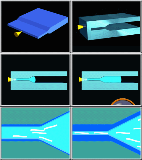
Place polymer injection locations in thicker regions of the part, preferably at a spot where the function and appearance of the part are not impaired. This causes the material to flow from the thickest areas to the thinnest areas, and helps maintain the flow and packing paths. Gating into thinner sections can result in hesitation or sink marks and voids.
The following animation shows how restrict material flow through a thin section can lead to material flow problems.

- Gate long, narrow parts from an end for uniform flow
-
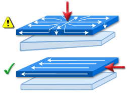
When a long narrow part is centrally gated, packing near the gate and variable molecular or fiber orientation throughout the part will cause differential shrinkage, which will warp the part. Gating a long part at one end will provide a uniform molecular and fiber orientation in the length direction. Although the end with the gate will be packed more than the opposite end, the resulting difference in shrinkage will not cause warpage.
The following figure shows the prefered injection location.

- Position the gate away from load-bearing areas
-
The high melt pressure and high velocity of flowing material at a gate causes that area to be highly stressed. For this reason, you should locate the gate away from load-bearing areas.
- Hide the gate scar
-
The removal of the gate will leave a mark on the part, which could be visually unacceptable. Place the gate so that the gate scar can be hidden or easily disguised.
- Vent properly to prevent air traps
-
The gate location should prevent air traps by enabling the air in the cavity to escape during injection. Failure to vent the air will result in a short shot, a burn mark on the molding, or high filling and packing pressure near the gates.
- Gate for proper weld-line location and strong weld lines
-
The gate location should cause weld and meld lines, if any, to form at appropriate positions that are not objectionable to the function, external load, or appearance of the part. Place the gate so that weld lines are formed early in the filling phase or at a high pressure area to ensure proper melding of the weld lines.
- Multiple gates shorten flow lengths
-
Add gates so that flow paths are within the flow limits for the thickness, distance, and process conditions. Each gate should have equal flow rates and volumes.