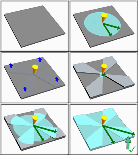
Molten plastic will preferentially flow through thicker sections of a mold, but subtle changes to the part geometry can help to balance the flow.
Flow leaders and deflectors
A flow leader is an increase in thickness along a flow path to increase the rate of flow along that path.
A flow deflector is a decrease in thickness along a flow path to decrease the rate of flow along that path.
Flow leaders and deflectors can be used to ensure all flow paths within the cavity fill at the same time to achieve balanced flow paths. Often the most suitable polymer injection location will not define equal flow paths, and the use of multiple polymer injection locations creates extra unwanted weld lines. Altering thicknesses within the design specifications is then the most appropriate way to balance the flow paths.
The following diagram of a square plate of uniform thickness with a polymer injection location in the center will demonstrate flow. The part on the left shows a radial flow pattern with unbalanced filling causing areas that fill early to be overpacked, which results in distortion problems. In the part on the right, the thickness of the plate has been increased from the center to the corners of the part, decreasing the resistance to flow in these directions

The following animation shows how changing the thicknesses in some sections of a part can create a more balanced flow pattern. The flow leaders and deflectors will create a fill pattern that is closer to a balanced flow, and additional refinements can be made to balance the flow further.

- Where possible, use flow deflectors instead of flow leaders to minimize the weight of the part.
- Shrinkage is a function of thickness so always consider the effects that changes in thickness might have on warpage.