The Warpage indicator, differential shrinkage result highlights those areas of the part where the out-of-plane deflections attributable to these differential shrinkage effects are approaching or exceeding the specified nominal maximum deflection (NMD) value.
One of the three contributors to warpage is variations in shrinkage from region to region within the part.
Using this result
The colors displayed in this plot are based on the following assessment criteria.
| Color (Assessment) | Explanation |
|---|---|
| Green (Low) | The out-of-plane deflections are less than 80 percent of the specified NMD value. The contribution of differential shrinkage effects to the warpage is low. |
| Yellow (Medium) | The out-of-plane deflections are between 80 percent and 120 percent of the specified NMD. The contribution of differential shrinkage effects to the warpage is significant. You should consider taking measures to reduce orientation in this area. |
| Red (High) | The out-of-plane deflections are greater than 120 percent of the specified NMD. Differential shrinkage effects are a key contributor to the warpage and corrective measures need to be taken. |
Things to look for
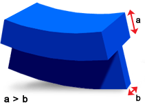
Differential shrinkage is often caused by variations in crystalline content and volumetric shrinkage. The following diagram shows a thin rib attached to a thick top. In general, the cooling rate of the top will be lower than that of the thin section. The top will have increased crystalline content and therefore, will shrink more and cause the warpage shown.

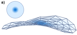
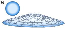
The following diagram (a) shows saddle warping of a centrally gated disk with high shrinkage around the gate. Conversely, if the shrinkage is higher around the outer part of the disk, the resulting warpage may cause the disk to dome, shown in (b).


= High Shrinkage
There are three main ways of influencing differential shrinkage effects.
If you have previously reduced orientation effects, the differential shrinkage effects may be quite different to those found in the original part model because of changes to gate locations or part thickness.
- Using a packing profile
- Reducing part thickness variations
- Using mold inserts
- Using a packing profile
-
The first option to consider when reducing differential shrinkage is the use of a packing profile. This depends on the machine response time and its effectiveness may be limited for thin parts or parts with complex geometries. The advantage of using a packing profile to reduce warpage is that this does not involve changing the design specifications of the part.
- Reducing part thickness variations
-
If you decide that changes to the wall thickness will reduce differential shrinkage effects for the part, you can alter the wall thickness and re-analyze the modified part model. This can be an iterative process until the differential shrinkage level is acceptable.
- Use mold inserts
-
The final method of reducing differential shrinkage is to use of mold inserts to reduce shrinkage due to variations in cooling rates. Mold insert analysis is only available in Autodesk Simulation Moldflow Insight.