CAD programs represent complex models by combining simpler surfaces together into the finished design.
When importing or meshing a part, the interface between these separate surfaces can be misinterpreted. This is the cause of many errors, especially in areas of fine detail. The inclusion of surface texture, small radii, or fillets, while important to the finished product, leads to unnecessary complexity in mesh generation.
- In the Entity Counts section, it is important to check the Connectivity regions value. There should only be one region. Any more than this will indicate disconnected sections of the part or runner system.
- In the Edge Details section, the integrity of the surface edges are determined.
Free edges are not connected to another surface. This value should be zero in Dual Domain and 3D meshes.
A manifold edge is a mesh edge that has two elements attached to it. This is the only edge type that is allowed for a Dual Domain mesh.
A non-manifold edge has more than two elements attached to it. For a Dual Domain mesh, this value should be zero.
- In the Orientation Details section, the Elements not oriented value should be zero. Orientation is not a meshing error but a data handling requirement of the program. This will be explained in the Mesh editing tutorial.
- In the Intersection Details section, shared surfaces are reported. All values should be zero.
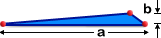
- The Surface Triangle Aspect Ratio section refers to the geometry of the mesh elements. The aspect ratio of an element is the ratio of the longest side to the height perpendicular to that side (a / b in the following figure).
 The aspect ratio value should ideally be less than:
For: Max. Aspect Ratio Midplane/Dual Domain 6:1 Midplane/Dual Domain-noncritical areas 20:1 Tetra elements 100:1 Dual Domain mesh before conversion to 3D 20:1 Cool and Warp analysis 6:1 Very high aspect ratio triangles should be avoided, especially when the longest side is in the direction of flow as this can affect localized results. The report indicates that there is at least one element with a high aspect ratio. You will investigate this later.
- In the Match Percentage section, the mesh match values should ideally be 85% or higher. Mesh matching is only applicable for Dual Domain meshes. This is a measure of how elements on one surface correspond with elements on the opposite surface. This measure is very important for correct part thickness determination and fiber orientation prediction.
The report shows that there are no major defects in the mesh (overlaps, intersections, disconnected elements) but that the aspect ratio of some elements needs improving.
In this task, you will:
- Create a Mesh Statistics report to assess the quality of the mesh you generated in the last task
- Run the Mesh Repair Wizard to check for and repair a number of common mesh defects
- Open the Mesh tutorial project you created in the previous task. Click
 and navigate to the project directory where your projects are stored.
 - From the Mesh_tutorial folder, select Mesh tutorial.mpi .
- Click Open.
- Click
 (). From the Tutorial folder, typically C:\Program Files\Autodesk\Simulation Moldflow Insight 20xx\tutorial, select mesh_tutorial5.sdy.
 - Click
 () to open the Mesh tab.
 - Click
 ().
(). - Click Close when you have finished reviewing the information in the Mesh Statistics dialog.
- You will now run the Mesh Repair Wizard to check for further mesh defects, and to try to correct the high aspect ratio elements automatically. Click
 (). The Mesh Repair Wizard opens at the Stitch Free Edges page.
 The wizard has automatically run a diagnostic to check for edges that are not connected to another edge. This is illustrated on the left of the dialog. There are "0 free edges found".
On each page of the wizard:- If a diagnostic indicates a problem, click Fix to try to correct the problem. Fix can be clicked repeatedly to correct problems.
- Click Skip to go to the next diagnostic without trying to fix the problem.
- Click Next to correct a mesh problem indicated by the current page of the wizard. By clicking Next, you can not see if the problem was resolved.
- Click Next to proceed to the Fill Hole page. The result indicates that there are no holes in the model.
- Click Next to proceed to the Overhang page. The result indicates that there are no elements that are not part of the model surface. This is a Dual Domain related issue only.
- Click Next to proceed to the Degenerate Elements page. A degenerate element has two nodes close to each other which can be resolved by merging nodes. (You would expect these elements to also have a high aspect ratio). For this model, no degenerate elements were found.
- Click Next to proceed to the Flip Normal page. The result indicates that all elements in the model are oriented consistently.
- Click Next to proceed to the Fix Overlap page. The result indicates that there are no intersections or overlapped surfaces in the model.
- Click Next to proceed to the Collapsed Faces page. Where boundaries on opposite surfaces unexpectedly touch, you have a collapsed surface. From an analysis point of view, a collapsed face represents an obstacle to the flow and so will impact on results in the local area. The result indicates that there is no collapse on the model boundary.
- Click Next to proceed to the Aspect Ratio page. As in the Mesh Statistics report, the minimum, maximum, and average aspect ratio values are reported.
- Select the Show diagnostics box to display the aspect ratio diagnostic plot in the Model display pane. An element with a high aspect ratio can be very thin and elongated, making it difficult to locate in the Model display pane. The Aspect Ratio Diagnostic plot therefore uses a special technique to help you locate high aspect ratio elements. The aspect ratio of each element is represented by a spike projecting from the center of the element. The longer the spike, the higher the aspect ratio. The color of the spike also indicates the magnitude of the aspect ratio. The color grid on the right of the pane is a guide to the aspect ratio value.
- Click Fix on the Aspect Ratio page to run the automatic repair function. The new results are reported on the dialog, and the plot is updated automatically. There are still some high aspect ratio elements that could not be fixed automatically.
- Examine the model after using the Mesh Repair Wizard. The wizard can fix most problems automatically. However, in some cases not all errors can be repaired, and new errors may be introduced. In the next task you will learn how to correct mesh errors manually.
- Click Next to proceed to the Summary page. The summary identifies the number of elements fixed and by what method.
- Click Close to exit the wizard.
- Save and close the study.
Click the Next topic link below to move on to the next task of the tutorial.