Launchpad app serves as a common entry point, or launchpad, for various design workflows.
The Autodesk Product Design Suite launchpad provides a single portal into Product Design Suite applications, project data, and workflows.
To open the launchpad, click Product Design Suite  . The version of Product Design Suite determines which applications and options are available on the launchpad.
Workflows tab Displays commonly used workflows for the applications available in Product Design Suite.
Applications tab Displays the applications that are available for your version of Product Design Suite.
Recent Files tab Displays a list of recently opened files, including the date, and application used.
Options
| 3D Parametric Design |
|
| Technical Drawing |
|
| Concept Sketching |
|
| Mold Design |
|
| Vault |
|
Machine Design
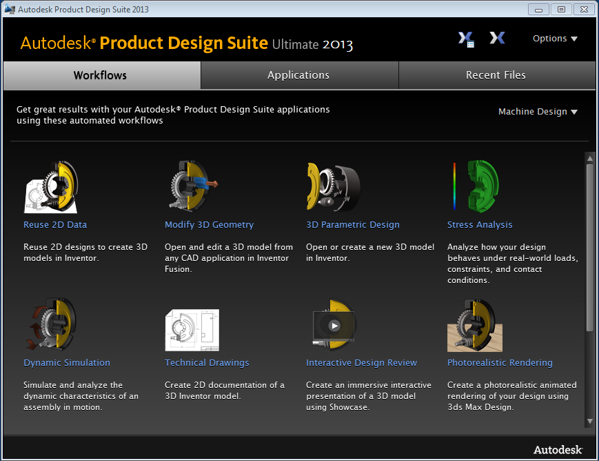
Workflow Descriptions
| Reuse 2D Data | Use 2D AutoCAD DWG data to start an Inventor 3D model. Select the DWG file to import and the layers to include. The 2D data is imported into a sketch in a new Inventor part file. The 2D data is now ready to be extruded, revolved or otherwise turned into a 3D model. |
| 3D Parametric Design | Open an existing 3D model, or create a 3D model in Autodesk Inventor. You can create a part or assembly. |
| Stress Analysis | The Inventor Stress Analysis environment simulates the structural behavior of your 3D model under specified loads and conditions. The selected Inventor part or assembly is loaded into the Stress Analysis environment where you can add loads and conditions to define the simulation. |
| Dynamic Simulation | To study the kinematic properties of your Inventor assembly, use the Inventor Dynamic Simulation environment. The selected assembly is loaded into the Dynamic Simulation environment and is ready to have loads and conditions applied. |
| Technical Drawings | Create 2D documentation of your 3D Inventor models. To generate the views and annotations, choose from either AutoCAD Mechanical or Inventor . |
| Interactive Design Review | Transform your 3D model into highly realistic imagery or perform an interactive presentation using Showcase. The selected part or assembly is loaded into Showcase. You can create design alternatives, configure lights and materials, then render the environment or use Showcase as a presentation environment. |
| Photorealistic Rendering | Create a photorealistic rendering or animation of your 3D model in 3ds Max Design. The selected Inventor part or assembly loads into 3ds Max Design. Then you can configure lights, materials, cameras, and other environment settings for your rendering or animation. |
| Large Assembly Review | Use parts and assemblies from many different sources to review and markup your design. Navisworks Simulate allows you to combine large assemblies into one environment to perform design reviews. Use <Ctrl> + select or <Shift> + select to select multiple files to load into Navisworks. |
| Cable & Harness Design | Create point-to-point wires in Inventor Cable & Harness using data from AutoCAD Electrical. AutoCAD Electrical can create an XML file with the required data to generate point-to-point wires in Inventor Cable & Harness. Then you can route these wires through your assembly to calculate wire lengths, or create a nailboard drawing. |
Plastic Part Design
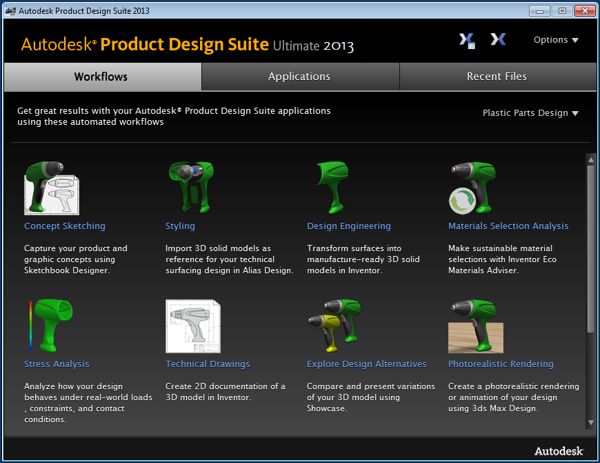
Workflow Descriptions
| Concept Sketching | Capture your product and graphic concepts using Sketchbook Designer. Sketchbook combines vector and raster workflows to provide an effective way to communicate design ideas. Start a blank sketch or import raster or AutoCAD DWG data. |
| Styling | Import an Inventor model or other 3D model into Alias Design to use as reference data for technical surfaces. The selected model is loaded into Alias Design where you can use it to build your surface data. |
| Design Engineering | Import Alias wire data into Inventor to transform your technical surface data into manufacture-ready solid models. Associativity is maintained so that Inventor consumes changes to the Alias .wire file. When there are issues with the imported data, the file opens in the Repair environment in Inventor, and is not associative to the original Alias file. Use the commands in the Repair environment to detect and fix the geometry. |
| Materials Selection Analysis | The selected 3D model is loaded into Inventor with the ECO Materials Adviser active. The ECO Materials Adviser evaluates environmental impact of your material selections so that you can make informed decisions. |
| Stress Analysis | The Inventor Stress Analysis environment simulates the structural behavior of your 3D model under specified loads and conditions. The selected Inventor part or assembly is loaded into the Stress Analysis environment where you can add loads and conditions to define the simulation. |
| Technical Drawings | Create 2D documentation of your 3D Inventor models. To generate the views and annotations, choose from either AutoCAD Mechanical or Inventor. |
| Explore Design Alternatives | Transform your 3D model into highly realistic imagery or perform an interactive presentation using Showcase. The selected part or assembly is loaded into Showcase. You can create design alternatives, configure lights and materials, then render the environment or use Showcase as a presentation environment. |
| Photorealistic Rendering | Create a photorealistic rendering or animation of your 3D model in 3ds Max Design. The selected Inventor part or assembly is loaded into 3ds Max Design. Then you can configure lights, materials, cameras, and other environment settings for your rendering or animation. |
| Cable & Harness Design | Create point-to-point wires in Inventor Cable & Harness using data from AutoCAD Electrical. AutoCAD Electrical can create an XML file with the required data to generate point-to-point wires in Inventor Cable & Harness. Then you can route these wires through your assembly to calculate wire lengths, or create a nailboard drawing. |
| Mold Design | Open an Inventor part file in the Inventor Mold Design environment. The selected part is loaded with the Adjust Orientation command active. After you set the orientation, you can begin designing you mold then analyze the design. |
Applications tab
Clicking the Applications tab lists all of the applications that installed with your version of Product Design Suite. To launch an application, besides using desktop icons or the Windows Start menu, you can click the program in the list. .
Recent Files tab
The Recent Files tab displays the most recently opened files in Product Design Suite. The filename, application that launched it, and the date and time it was last opened display in three columns. In the Filename column, click a file to launch the associated application, and open the file.