Extrusion Analysis of a Solid
The utility class ExtrusionAnalyzer allows you to attempt to “fit” a given piece of geometry into the shape of an extruded profile. An instance of this class is a single-time use class which should be supplied a solid geometry, a plane, and a direction. After the ExtrusionAnalyzer has been initialized, you can access the results through the following members:
- The GetExtrusionBase() method returns the calculated base profile of the extruded solid aligned to the input plane.
- The CalculateFaceAlignment() method can be used to identify all faces from the original geometry which do and do not align with the faces of the calculated extrusion. This could be useful to figure out if a wall, for example, has a slanted join at the top as would be the case if there is a join with a roof. If a face is unaligned, something is joined to the geometry that is affecting it.
- To determine the element that produced the non-aligned face, pass the face to Element.GetGeneratingElementIds(). For more details on this utility, see the following section.
The ExtrusionAnalyzer utility works best for geometry which are at least somewhat “extrusion-like”, for example, the geometry of a wall which may or may not be affected by end joins, floor joins, roof joins, openings cut by windows and doors, or other modifications. Rarely for specific shape and directional combinations the analyzer may be unable to determine a coherent face to act as the base of the extrusion – an InvalidOperationException will be thrown in these situations.
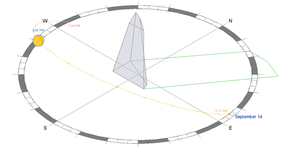
In this example, the extrusion analyzer is used to calculate and outline a shadow formed from the input solid and the sun direction.
|
Code Region: Use Extrusion Analyzer to calculate and draw a shadow outline. |
/// <summary>
/// Draw the shadow of the indicated solid with the sun direction specified.
/// </summary>
/// <remarks>The shadow will be outlined with model curves added to the document.
/// A transaction must be open in the document.</remarks>
/// <param name="document">The document.</param>
/// <param name="solid">The target solid.</param>
/// <param name="targetLevel">The target level where to measure and
/// draw the shadow.</param>
/// <param name="sunDirection">The direction from the sun (or light source).</param>
/// <returns>The curves created for the shadow.</returns>
/// <throws cref="Autodesk.Revit.Exceptions.InvalidOperationException">
/// Thrown by ExtrusionAnalyzer when the geometry and
/// direction combined do not permit a successful analysis.</throws>
private static ICollection<ElementId> DrawShadow(Document document, Solid solid,
                                                 Level targetLevel, XYZ sunDirection)
{
    // Create target plane from level.
    Plane plane = document.Application.Create.NewPlane(XYZ.BasisZ,
                                   new XYZ(0, 0, targetLevel.ProjectElevation));

    // Create extrusion analyzer.
    ExtrusionAnalyzer analyzer = ExtrusionAnalyzer.Create(solid, plane, sunDirection);

    // Get the resulting face at the base of the calculated extrusion.
    Face result = analyzer.GetExtrusionBase();

    // Convert edges of the face to curves.
    CurveArray curves = document.Application.Create.NewCurveArray();
    foreach (EdgeArray edgeLoop in result.EdgeLoops)
    {
        foreach (Edge edge in edgeLoop)
        {
            curves.Append(edge.AsCurve());
        }
    }

    // Get the model curve factory object.
    Autodesk.Revit.Creation.ItemFactoryBase itemFactory;
    if (document.IsFamilyDocument)
        itemFactory = document.FamilyCreate;
    else
        itemFactory = document.Create;

    // Add a sketch plane for the curves.
    SketchPlane sketchPlane =
       itemFactory.NewSketchPlane(document.Application.Create.NewPlane(curves));
    document.Regenerate();

    // Add the shadow curves
    ModelCurveArray curveElements = itemFactory.NewModelCurveArray(curves, sketchPlane);

    // Return the ids of the curves created
    List<ElementId> curveElementIds = new List<ElementId>();
    foreach (ModelCurve curveElement in curveElements)
    {
        curveElementIds.Add(curveElement.Id);
    }

    return curveElementIds;
}
|
The utility above above can be used to compute the shadow of a given mass with respect to the current sun and shadows settings for the view:
