A profile family contains a 2-dimensional shape (usually a closed loop) that you can load into a project and apply to certain building elements. For example, you can sketch the profile loop for a railing and then use that shape on a railing in your project. Loaded profiles display in the Project Browser under Families.
To create a profile family, open a new family, and sketch a profile using lines, dimensions, and reference planes. After you save the profile family, you can load it and apply it to solid geometry in the project.
This procedure describes creating a generic profile shape that is available to multiple building elements in the project. Your specific building and design intentions may differ.
To create a profile
- Click

 NewFamily.
 - In the New Family - Select Template File dialog, select a profile template, and click Open.
The Family Editor opens a plan view that includes 2 reference planes. There are no other views available in which to sketch lines.
- If necessary, sketch reference planes for constraining the lines in the profile.
- Click Create tabDetail panel
 (Line), and sketch the profile loop.
 - If necessary, click Create tabDetail panel
 (Detail Component) to place a detail component into the profile family. Tip: You can change the sorting order of any detail components in the family by using the detail component draw order tools.
 - To specify the detail at which the profile family displays in the project, select any of the lines of the profile sketch, and click Modify | Lines tabVisibility panel
 (Visibility Settings).
 - Select the desired detail levels (Fine, Medium, or Coarse), and click OK. Tip: You can specify the detail level for detail components using the same methods.
- On the Properties palette, under Other, for Profile Usage, click in the Value field, and select the profile type.
For example, if you are creating a mullion profile, select Mullion.
Tip: This setting ensures that only relevant profiles are listed when using profiles within a project. For example, when selecting a mullion profile, stair nosing profiles do not display. - Click Apply.
- Add any dimensions required.
- Save the family.
Examples
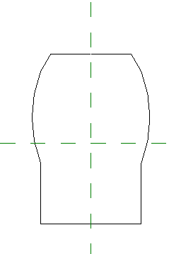
Sample profile sketch
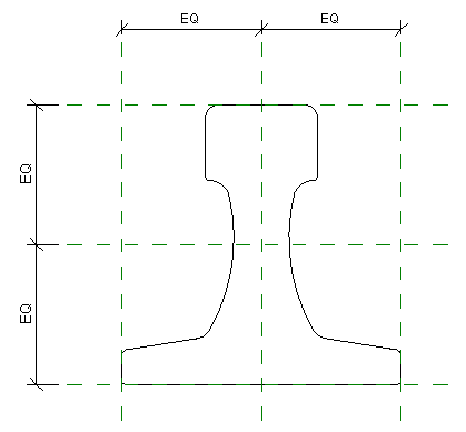
Sample crane rail profile sketch
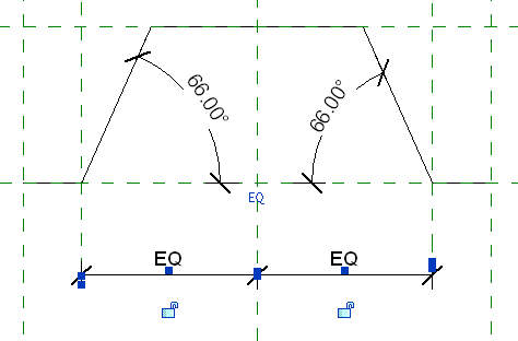
Sample metal deck profile sketch