- Click

 New
New Family.
 - In the New Family dialog, select a default family template (for example, Plumbing Fixture wall based.rft), and click Open.
- Open the view to import the DWG file into.
For example, if you have a DWG file for a plan representation, open the plan view.
- Click Insert tab
 Import panel
 (Import CAD).
 - In the Import CAD Formats dialog, navigate to the DWG file.
If you only want the representation to be visible in plan view, select the Current View Only option. Also, if you are unsure of the original coordinates of the DWG file, for Positioning, select Manual - Center.
- Click Open.
- Click in the drawing area to place the import symbol.
- Modify the position of the import symbol as necessary, and lock the symbol to the necessary reference planes.
- Click Annotate tab
 Detail panel
 (Masking Region).
 - Sketch the masking region. Attention: When a model family only contains 2D elements and you are adding a masking region to a 2D element, you must include an invisible line to represent the Z dimension, which is where the masking region is drawn. The invisible line must be drawn above the level and must be a minimal length (such as 1/8”) so that the masking region does not obscure any other elements in the view.
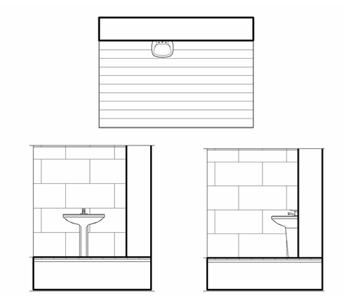
- Add any other 2D view representations (for example, front elevation and side elevation) and masking regions, as necessary.
- When finished, click
 on the Quick Access toolbar to save the family.
 - If you need to load the family into a project, click Create tab
 Family Editor panel
 (Load into Project).
 If you have only one project open, the family loads into that project. If you have multiple projects open, the Load into Projects dialog opens where you can select the projects to load the family into.
When you load the family into a project and place it in the drawing area, it obscures surface patterns in orthogonal views.
Example
