The values that are entered on this tab reflect the plotted representation of the drawings. Therefore, the visible representations that are set with these values will change based on the view scale of the drawing.
Open the Structural Settings dialog:
Modify symbolic cutback distance:
Plan representation options:
Show brace above
Show brace below
Kicker brace symbol
Loading and Assigning Connection Symbol Families
- On the ribbon, click Structural Settings.
- Structure tab
 Structure panel

- Manage tab
 Settings panel
 Structural Settings
Where is it?
- Structure tab
- On the Symbolic Representation Settings tab, enter values for the symbolic cutback distances for braces and beams.

These settings affect the distance between steel beams and beams/trusses, and between beams and braces.
Members must be joined to see the change in the cutback distance. Changes to these settings are applied only to the symbolic representation of structural framing components.
Examples

Cutback distance at larger setting in coarse mode

Cutback distance at smaller setting in coarse mode
- Enter a value for the symbolic column cutback distance.
This setting affects the gap between symbolic representations of joined columns in an elevation view. The gap is visible only if the Top Connection Symbol instance property of the bottom column is set to a value other than None.
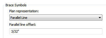
- Under Brace Symbols, select a value for Plan representation.

Plan Representation options
- Parallel Line:
Symbolic representation of braces in a plan view are displayed with a line parallel to and offset from the brace at the value specified in the Structural Settings dialog. The line displays below, or to the right to vertical brace centerline if the brace is below the level and above, or to the left to vertical brace centerline if the brace is above the level.
 Note: The parallel line brace symbol displays in a symbolic plan view only when the structural usage of the brace is set to Vertical Bracing.
 - Line with Angle:
Symbolic representation of braces in a plan view are displayed with an angled line. Line with angle originates from the point of intersection of a brace and level if they intersect, and from the closest point to the level on the brace otherwise. The symbol goes upward (downward) for the portion of the brace which is above (below) the level.
 Note: The line with angle brace symbol displays in a symbolic plan view only when the structural usage of the brace is set to Vertical Bracing.
- Parallel Line:
- Under Brace Symbols, specify Parallel line offset.
This value is available only after selecting Parallel Line for Plan representation. The parallel line is offset the specified value from the vertical brace centerline.
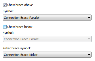
Note: You can create new brace representation symbols using the generic annotation template. In the Family Category and Parameters dialog, set their Family Category to Brace in Plan View Symbols. Brace in Plan View symbols have a Representation Type parameter that can be either Parallel Line, Line with Angle, or Kicker Brace. - Under Brace Symbols, select Show brace above if you want the brace symbols representing the braces above the current view to display.

- For Symbol, select the symbol that represents braces above the current view. Note: The brace above symbol changes automatically when you change the plan representation from parallel line to angle line.
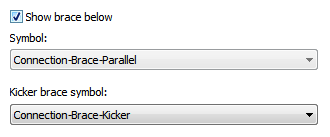
- Under Brace Symbols, select Show brace below if you want the brace symbols representing the braces below the current view to display.

- For Symbol, select the symbol that represents braces below the current view. Note: The brace below symbol changes automatically when you change the plan representation from parallel line to angle line.
- Under Brace Symbols, select the symbol that represents kicker bracing. Note: The kicker brace symbol displays in a symbolic plan view only when the structural usage of the brace is set to Kicker Bracing.
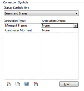
- In the Connection Symbols section, select Display Symbols for Beams and Braces.

- Click Load.
- Navigate to the Annotations/Structural directory, select a connection symbol family, and click Open.
- Select the Annotation Symbol from the drop-down for the Connection Type.
- Click OK. Note: Use the following tools to manage your connection types.
 (Add a connection type)
 Opens the New Connection Type dialog. Name and assign an annotation symbol to the connection type. You can optionally load a new symbol, if needed. Click OK to continue.  (Duplicate a connection type)
 Duplicates a selected connection type.
Rename and assign an Annotation Symbol as needed.
 (Rename a connection type)
 Opens the Rename dialog to change the name of the selected connection type.  (Delete a connection type)
 Deletes the selected connection type.
Connection symbols display at the ends of the symbol of beams, braces, and columns. You can define your own connection types, and assign a connection symbol family to each type. The types are divided into beam/brace end connections, column top connections, and column base connections.