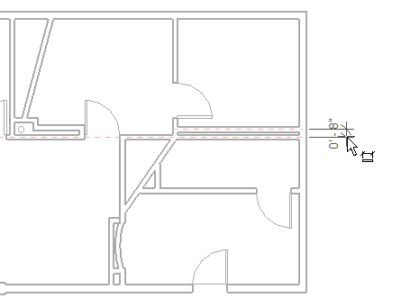
Interior and exterior room-bounding components must be correctly identified to create an accurate heating and cooling loads analysis. Whenever possible, you should place a space component in cavities, shafts, and chases. However, some areas are too small to allow placing a space. When this occurs, you can account for the volume of these small spaces using one of two methods:
- Clear the Room Bounding parameter for a wall that is tangent to another space. This includes the volume of the smaller area in the volume for the larger adjacent area.
- Modify the Sliver Space Tolerance to treat the area as a sliver space. This automatically includes the volume for all areas in the model that fall within the sliver tolerance in the volume for an adjacent area.
The size and shape of these small areas determines how to account for the volume.
Clear Room-Bounding parameters
- Right-click the wall between a space and the small area, and click Properties from the context menu.
- On the Properties palette, under Constraints, clear Room Bounding.
- Click OK.
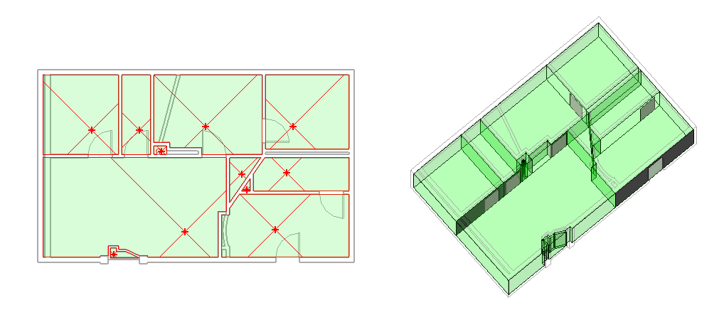
The shading for the tangent space fills both areas and the volume for the cavity, shaft or chase is automatically included in the tangent space.
- Repeat to clear the room-bounding parameter for similar areas in the model. Note: When working with a linked model, you must clear the room-bounding parameter in the linked model.
Treat the area as a sliver space
- Review the description of sliver spaces before adjusting the Sliver Space Tolerance.
It’s often safer to clear the room-bounding parameter for a particular space than to apply the Sliver Space Tolerance throughout the model.
- Click Annotate tab
 Dimension panel
 Linear, and determine the distance between the centerlines of the room-bounding walls enclosing the sliver.
- Click Manage tab
 Settings panel
 .
. - On the Properties palette, under Energy Analysis, click Edit.
- In Energy Settings dialog, specify a Sliver Space Tolerance that is equal to or greater than the distance between the wall centerlines.

The illustration above shows a model that is ready for loads analysis. It shows the floor plan to the left and the analytical model created in the Heating and Cooling Loads dialog to the right. Spaces have been placed for all of the symmetrical and asymmetrical areas, including the in-place component placed in the opening at the bottom of the model. The space (far left) is not a sliver, because no space exists to the left of the outer wall. The room-bounding parameter was cleared for the wall separating this area from the tangent spaces. The room-bounding parameter was also cleared for the walls separating the curved area and small rectangular area at the lower center of the project. When the room-bounding parameter is cleared, the shading displays for these areas as part of the tangent spaces. Sliver spaces display unshaded in the floor plan view. However, the sliver spaces do display in the analytical model (in the Heating and Cooling Loads dialog), and they are computed during heating and cooling loads analysis.