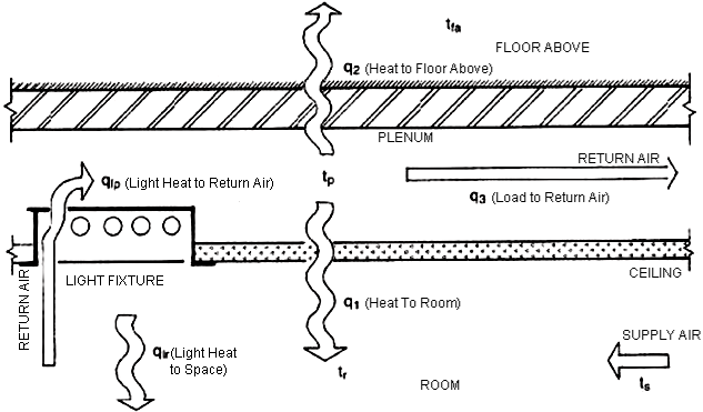
The space above a ceiling, when used as a return air path, is a ceiling return air plenum. Unlike a traditional ducted return, the plenum may have multiple heat sources in the path. These heat sources may be radiant and convective loads from lighting and transformers; conduction loads from adjacent walls, roofs, or glazing; or duct and piping systems within the plenum. The following equations show how temperatures and heat transfer for plenums are calculated in the engine:
![]() (35)
(35)
![]() (36)
(36)
![]() (37)
(37)
![]() (38)
(38)
 (39)
(39)
where
![]() = heat gain to space from plenum through ceiling, Btu/h
= heat gain to space from plenum through ceiling, Btu/h
![]() = heat loss from plenum through floor above, Btu/h
= heat loss from plenum through floor above, Btu/h
![]() = heat gain “pickup” by return air, Btu/h
= heat gain “pickup” by return air, Btu/h
![]() = return airflow, Btu/h
= return airflow, Btu/h
![]() = light heat gain to plenum via return air, Btu/h
= light heat gain to plenum via return air, Btu/h
![]() = light heat gain to space, Btu/h
= light heat gain to space, Btu/h
![]() = heat gain from plenum below, through floor, Btu/h
= heat gain from plenum below, through floor, Btu/h
![]() = heat gain from exterior wall, Btu/h
= heat gain from exterior wall, Btu/h
![]() = space cooling load, including appropriate treatment of
= space cooling load, including appropriate treatment of ![]() ,
, ![]() and/or
and/or ![]() , Btu/h
, Btu/h
![]() = plenum temperature, °F
= plenum temperature, °F
![]() = space temperature, °F
= space temperature, °F
![]() = space temperature of the floor above, °F
= space temperature of the floor above, °F
![]() = supply temperature, °F
= supply temperature, °F

Schematic Diagram of Typical Return Air Plenum