Structural Model Elements
Structural Model Elements are, literally, elements that support a structure such as columns, rebar, trusses, and so on. This section discusses how to manipulate these elements.
Column, Beam, and Brace
Structural column, beam, and brace elements do not have a specific class such as the StructuralColumn class but they are in the FamilyInstance class form.
NoteThough the StructuralColumn, StructuralBeam, and StructuralBrace classes do not exist in the current API, they are used in this chapter to indicate the FamilyInstance objects corresponding to structural columns, beams, and braces.Though Structural column, beam, and brace are all FamilyInstance objects in the API, they are distinguished by the StructuralType property.
|
Code Region 29-1: Distinguishing between column, beam and brace |
public void GetStructuralType(FamilyInstance familyInstance)
{
        string message = "";
        switch (familyInstance.StructuralType)
        {
                case StructuralType.Beam:
                        message = "FamilyInstance is a beam.";
                        break;
                case StructuralType.Brace:
                        message = "FamilyInstance is a brace.";
                        break;
                case StructuralType.Column:
                        message = "FamilyInstance is a column.";
                        break;
                case StructuralType.Footing:
                        message = "FamilyInstance is a footing.";
                        break;
                default:
                        message = "FamilyInstance is non-structural or unknown framing.";
                        break;
        }
        TaskDialog.Show("Revit", message);
}
|
You can filter out FamilySymbol objects corresponding to structural columns, beams, and braces in using categories. The category for Structural beams and braces is BuiltInCategory.OST_StructuralFraming.
|
Code Region 29-2: Using BuiltInCategory.OST_StructuralFraming |
public void GetBeamAndColumnSymbols(Document document)
{
        FamilySymbolSet columnTypes = new FamilySymbolSet();
        FamilySymbolSet framingTypes = new FamilySymbolSet();
        FilteredElementCollector collector = new FilteredElementCollector(document);
        ICollection<Element> elements = collector.OfClass(typeof(Family)).ToElements();

        foreach(Element element in elements)
        {

                Family tmpFamily = element as Family;
                Category category = tmpFamily.FamilyCategory;
                if (null != category)
                {
                        if ((int)BuiltInCategory.OST_StructuralColumns == category.Id.IntegerValue)
                        {
                                foreach (FamilySymbol tmpSymbol in tmpFamily.Symbols)
                                {
                                        columnTypes.Insert(tmpSymbol);
                                }
                        }
                        else if ((int)BuiltInCategory.OST_StructuralFraming == category.Id.IntegerValue)
                        {
                                foreach (FamilySymbol tmpSymbol in tmpFamily.Symbols)
                                {
                                        framingTypes.Insert(tmpSymbol);
                        }
                }
        }
}
        string message = "Column Types: ";
        FamilySymbolSetIterator fsItor = columnTypes.ForwardIterator();
        fsItor.Reset();
        while (fsItor.MoveNext())
        {
                FamilySymbol familySybmol = fsItor.Current as FamilySymbol;
                message += "\n" + familySybmol.Name;
        }
        TaskDialog.Show("Revit",message);
}
|
You can get and set beam setback properties with the FamilyInstance.ExtensionUtility property. If this property returns null, the beam setback can't be modified.
AreaReinforcement and PathReinforcement
Find the AreaReinforcementCurves for AreaReinforcement by calling the GetCurveElementIds() method which returns an IList of ElementIds that represent AreaReinforcementCurves. In edit mode, AreaReinforcementCurves are the purple curves (red when selected) in the Revit UI. From the Element Properties dialog box you can see AreaReinforcementCurve parameters. Parameters such as Hook Types and Orientation are editable only if the Override Area Reinforcement Setting parameter is true.
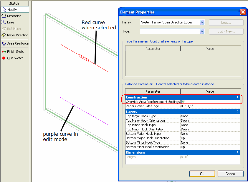
Figure 154: AreaReinforcementCurve in edit mode
The Major Direction of the area reinforcement can be set when creating a new AreaReinforcement using the NewAreaReinforcement() method (the last XYZ direction input parameter) and by using the AreaReinforcement.Direction property.
|
Code Region 29-3: NewAreaReinforcement() |
public AreaReinforcement NewAreaReinforcement(
        Element host, CurveArray curves, XYZ direction);
|
Although the AreaReinforcement.GetCurveElementIds() method returns a set of ElementIds representing AreaReinforcementCurves, which have a property that returns a Curve, the PathReinforcement.GetCurveElementIds() method returns a collection of ElementIds that represent ModelCurves. There is no way to flip the PathReinforcement except by using the NewPathReinforcement() method (the last input parameter).
|
Code Region 29-4:NewPathReinforcement() |
public PathReinforcement NewPathReinforcement(
        Element host, CurveArray curves, bool flip);
|
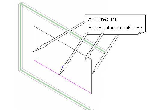
Figure 155: PathReinforcement.PathReinforcementCurve in edit mode
When using NewAreaReinforcement() and NewPathReinforcement() methods to create objects, you must decide on which host Element face it will lay. Currently AreaReinforcement and PathReinforcement are only created on the PlanarFace retrieved from the Wall or Floor object. After removing the faces from the Wall or Floor geometry, you can filter the PlanarFace out as follows:
- Downcast the Face to PlanarFace:
Code Region 29-5: Downcasting Face to PlanarFace
PlanarFace planarFace = face as PlanarFace;
- If it is a PlanarFace, get its Normal and Origin:
Code Region 29-6: Getting Normal and Origin
private void GetPlanarFaceInfo(Face face) { PlanarFace planarFace = face as PlanarFace; if (null != planarFace) { XYZ origin = planarFace.Origin; XYZ normal = planarFace.Normal; XYZ vector = planarFace.get_Vector(0); } } - Filter out the right face based on normal and origin. For example:
- For a general vertical Wall, the face is located using the following factors:
- The face is vertical; (normal.Z == 0.0)
- Parallel face directions are opposite:
- (normal1.X = - normal2.X; normal1.Y = - normal2.Y)
- Normal must be parallel to the location line.
- For a general Floor without slope, the factors are:
- The face is horizontal; (normal.X == 0.0 && normal.Y ==0.0)
- Judge the top and bottom face; (distinguish 2 faces by normal.Z)
- For a general vertical Wall, the face is located using the following factors:
For more details about retrieving an Element's Geometry, refer to Geometry.
Note that project-wide settings related to area and path reinforcement are accessible from the ReinforcementSettings class. Currently, the only setting available is the HostStructuralRebar property.BeamSystem
BeamSystem provides you with full access and edit ability. You can get and set all of its properties, such as BeamSystemType, BeamType, Direction, and Level. BeamSystem.Direction is not limited to one line of edges. It can be set to any XYZ coordinate on the same plane with the BeamSystem.
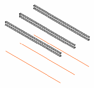
Figure 156: Change BeamSystem elevation
Truss
The Truss class represents all types of trusses in Revit. The TrussType property indicates the type of truss.
|
Code Region 29-7: Creating a truss over two columns |
Truss CreateTruss(Autodesk.Revit.DB.Document document,
    FamilyInstance column1, FamilyInstance column2)
{
    Truss truss = null;
    using (Transaction transaction = new Transaction(document, "Add Truss"))
    {
       if (transaction.Start() == TransactionStatus.Started)
       {
           //sketchPlane
           XYZ origin = new XYZ(0, 0, 0);
           XYZ xDirection = new XYZ(1, 0, 0);
           XYZ yDirection = new XYZ(0, 1, 0);
           Plane plane = document.Application.Create.NewPlane(xDirection, yDirection, origin);
           SketchPlane sketchPlane = SketchPlane.Create (document, plane);

           //new base Line - use line that spans two selected columns
           AnalyticalModel frame1 = column1.GetAnalyticalModel() as AnalyticalModel;
           XYZ centerPoint1 = (frame1.GetCurve() as Line).GetEndPoint(0);

           AnalyticalModel frame2 = column2.GetAnalyticalModel() as AnalyticalModel;
           XYZ centerPoint2 = (frame2.GetCurve() as Line).GetEndPoint(0);

           XYZ startPoint = new XYZ(centerPoint1.X, centerPoint1.Y, 0);
           XYZ endPoint = new XYZ(centerPoint2.X, centerPoint2.Y, 0);
           Autodesk.Revit.DB.Line baseLine = null;

           try
           {
               baseLine = Line.CreateBound(startPoint, endPoint);
           }
           catch (System.ArgumentException)
           {
               throw new Exception("Selected columns are too close to create truss.");
           }

           // use the active view for where the truss's tag will be placed; View used in
           // NewTruss should be plan or elevation view parallel to the truss's base line
           Autodesk.Revit.DB.View view = document.ActiveView;

           // Get a truss type for the truss
           FilteredElementCollector collector = new FilteredElementCollector(document);
           collector.OfClass(typeof(FamilySymbol));
           collector.OfCategory(BuiltInCategory.OST_Truss);

           TrussType trussType = collector.FirstElement() as TrussType;

           if (null != trussType)
           {
               truss = Truss.Create(document, trussType.Id, sketchPlane.Id, baseLine);
               transaction.Commit();
           }
           else
           {
               transaction.RollBack();
               throw new Exception("No truss types found in document.");
           }
       }
    }

    return truss;
}
|
Rebar
The Rebar class represents rebar used to reinforce suitable elements, such as concrete beams, columns, slabs or foundations.
You can create rebar objects using one of three static Rebar methods.
|
Name |
Description |
public static Rebar Rebar.CreateFromCurves(
        Document doc,
        RebarStyle style,
        RebarBarType rebarType,
        RebarHookType startHook,
        RebarHookType endHook,
        Element host,
        XYZ norm,
        IList<Curve> curves,
        RebarHookOrientation startHookOrient,
        RebarHookOrientation endHookOrient,
        bool useExistingShapeIfPossible,
        bool createNewShape
);
|
Creates a new instance of a Rebar element within the project. All curves must belong to the plane defined by the normal and origin. |
public static Rebar Rebar.CreateFromRebarShape(
        Document doc,
        RebarShape rebarShape,
        RebarBarType rebarType,
        Element host,
        XYZ origin,
        XYZ xVec,
        XYZ yVec
);
|
Creates a new Rebar, as an instance of a RebarShape. The instance will have the default shape parameters from the RebarShape, and its location is based on the bounding box of the shape in the shape definition. Hooks are removed from the shape before computing its bounding box. If appropriate hooks can be found in the document, they will be assigned arbitrarily. |
public static Rebar Rebar.CreateFromCurvesAndShape(
        Document doc,
        RebarShape rebarShape,
        RebarBarType rebarType,
        RebarHookType startHook,
        RebarHookType endHook,
        Element host,
        XYZ norm,
        IList<Curve> curves,
        RebarHookOrientation startHookOrient,
        RebarHookOrientation endHookOrient
);
|
Creates a new instance of a Rebar element within the project. The instance will have the default shape parameters from the RebarShape. All curves must belong to the plane defined by the normal and origin. |
The first version creates rebar from an array of curves describing the rebar, while the second creates a Rebar object based on a RebarShape and position. The third version creates rebar from an array of curves and based on a RebarShape.
When using the CreateFromCurves() or CreateFromCurvesAndShape() method, the parameters RebarBarType and RebarHookType are available in the RebarBarTypes and RebarHookTypes properties of the Document.
The following code illustrates how to create Rebar with a specific layout.
|
Code Region 29-8: Creating rebar with a specific layout |
Rebar CreateRebar(Autodesk.Revit.DB.Document document, FamilyInstance column, RebarBarType barType, RebarHookType hookType)
{
    // Define the rebar geometry information - Line rebar
    LocationPoint location = column.Location as LocationPoint;
    XYZ origin = location.Point;
    XYZ normal = new XYZ(1, 0, 0);
    XYZ rebarLineEnd = new XYZ(origin.X, origin.Y, origin.Z + 9);
    Line rebarLine = Line.CreateBound(origin, rebarLineEnd);

    // Create the line rebar
    IList<Curve> curves = new List<Curve>();
    curves.Add(rebarLine);

    Rebar rebar = Rebar.CreateFromCurves(document, Autodesk.Revit.DB.Structure.RebarStyle.Standard, barType, hookType, hookType,
                        column, origin, curves, RebarHookOrientation.Right, RebarHookOrientation.Left, true, true);

    if (null != rebar)
    {
        // set specific layout for new rebar
        Parameter paramLayout = rebar.get_Parameter(BuiltInParameter.REBAR_ELEM_LAYOUT_RULE);
        paramLayout.Set(1); // 1 = Fixed Number
        Parameter paramNum = rebar.get_Parameter(BuiltInParameter.REBAR_ELEM_QUANTITY_OF_BARS);
        paramNum.Set(10);
        rebar.ArrayLength = 1.5;
    }

    return rebar;
}
|
The following table lists the integer value for the Parameter REBAR_ELEM_LAYOUT_RULE:
Table 59: Rebar Layout Rule
|
Value |
0 |
1 |
2 |
3 |
4 |
|
Description |
None |
Fixed Number |
Maximum Spacing |
Number with Spacing |
Minimum Clear Spacing |
RebarHostData and RebarCoverType
Clear cover is associated with individual faces of valid rebar hosts. You can access the cover settings of a host through the Autodesk.Revit.Elements.RebarHostData object. A simpler, less powerful mechanism for accessing the same settings is provided through parameters.
Cover is defined by a named offset distance, modeled as an element Autodesk.Revit.DB.Structure.RebarCoverType.
BoundaryConditions
There are three types of BoundaryConditions:
- Point
- Curve
- Area
The type and pertinent geometry information is retrieved using the following code:
|
Code Region 29-9: Getting boundary condition type and geometry |
public void GetInfo_BoundarySegment(Room room)
{
    IList<IList<Autodesk.Revit.DB.BoundarySegment>  segments = room.GetBoundarySegments(new SpatialElementBoundaryOptions());

    if (null != segments)  //the room may not be bound
    {
        string message = "BoundarySegment";
        foreach (IList<Autodesk.Revit.DB.BoundarySegment> segmentList in segments)
        {
            foreach (Autodesk.Revit.DB.BoundarySegment boundarySegment in segmentList)
            {

                // Get curve start point
                message += "\nCurve start point: (" + boundarySegment.Curve.GetEndPoint(0).X + ","
                                + boundarySegment.Curve.GetEndPoint(0).Y + "," +
                                boundarySegment.Curve.GetEndPoint(0).Z + ")";
                // Get curve end point
                message += ";\nCurve end point: (" + boundarySegment.Curve.GetEndPoint(1).X + ","
                        + boundarySegment.Curve.GetEndPoint(1).Y + "," +
                        boundarySegment.Curve.GetEndPoint(1).Z + ")";
                // Get document path name
                message += ";\nDocument path name: " + boundarySegment.Document.PathName;
                // Get boundary segment element name
                if (boundarySegment.Element != null)
                {
                    message += ";\nElement name: " + boundarySegment.Element.Name;
                }
            }
        }

        TaskDialog.Show("Revit",message);
    }
}
|
Other Structural Elements
Some Element derived classes exist in Revit Architecture and Revit Structure products. In this section, methods specific to Revit Structure are introduced. For more information about these classes, see the corresponding parts in Walls, Floors, Roofs and Openings and Family Instances.
Slab
Both Slab (Structural Floor) and Slab Foundation are represented by the Floor class and are distinguished by the IsFoundationSlab property.
The Slab Span Directions are represented by the IndependentTag class in the API and are available as follows:
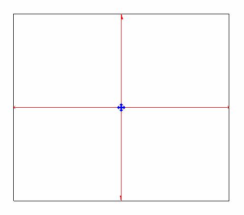
Figure 157: Slab span directions
When using NewSlab() to create a Slab, Span Directions are not automatically created. There is also no way to create them directly.
The Slab compound structure layer Structural Deck properties are exposed by the following properties:
- CompoundStructuralLayer.DeckUsage
- DeckProfile
The properties are outlined in the following dialog box:
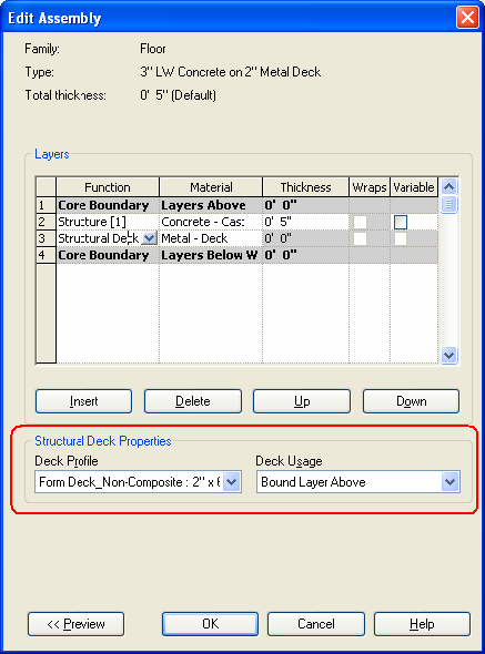
Figure 158: Floor CompoundStructuralLayer properties