Before describing how structural framing elements join, attach, and cut back from one another, it is important to understand how component families are perceived in a project. Each element instance is enclosed in a bounding box.
Overview
The bounding box is an invisible 3D rectangular space that contains all model elements, annotation elements, and datum elements defined in a family-based element. Datum extents are the exception. For example, a horizontal reference plane will only affect a top or bottom of the bounding box, not either of its sides. The bounding box is oriented with respect to the family definition.

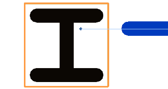
Bounding boxes of columns represented in orange
The top, bottom, and sides of the bounding box rotate accordingly to maintain its relationship with the element as it rotates.

Bounding boxes rotating with elements
General purposes of the bounding box
- If a family does not have a family origin explicitly defined, the origin will default to the center of the bounding box. This origin affects placement of instances and their behavior when the instance type or family is changed. For detailed information about family origins, see Defining the Family Origin.
- The bounding box helps define the joining and cutback of structural framing elements.
Beam to Column Joins
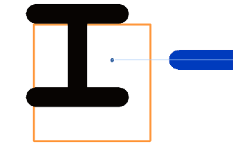
The following illustration shows an example of a beam that is not centered on a column. The beam handle of the beam in the illustration remains within a bounding box. Remember, the bounding box is not visible.

If the column is moved slightly, but not completely out of its existing bounding box, the beam handle remains in position, unaffected by column movement.

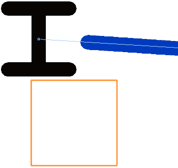
However, if the column is moved out of its bounding box, the beam handle snaps to the center of the column. When placed, the column will maintain a bounding box.

Curved Beams
Curved beams present a unique instance of the bounding box. The bounding box bends to meet the needs of the beam. This provides accurate joining and cutback with the beam.
