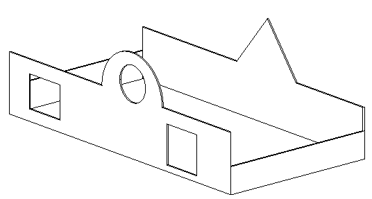
In most cases, when you place a straight wall, it has a rectangular profile when viewed in elevations parallel to its length. If your design calls for a different shape of profile, or for openings in the wall, use the following procedure to edit the wall’s elevation profile in either a section or elevation view.

Design with non-rectangular walls and cut openings
To edit the profile of a wall
- In the drawing area, select the wall, and click Modify | Walls tab
 Mode panel
 Edit Profile.
 - If the active view is a plan view, the Go To View dialog displays, prompting you to select an appropriate elevation or section view. For example, for a north wall, you could select either the North or South elevation view.
When an appropriate view is open, the profile of the wall displays in magenta model lines, as shown.

- Use the tools on the Modify and Draw panels to edit the profile as needed.
- Delete the lines and then sketch a completely different shape.
- Split the existing lines and add arcs.
- Draw openings or holes.

Wall modified
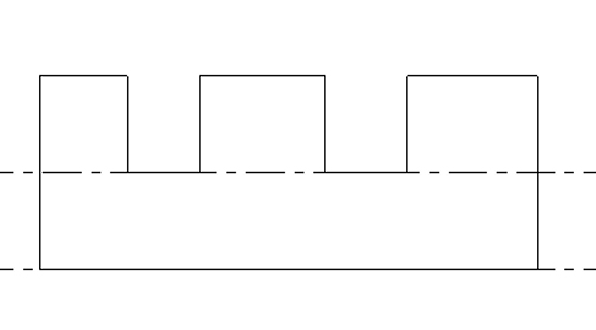
Tip: As you move and edit the rectangle, datum planes appear to indicate the original shape and size of the wall when you entered sketch mode. If the sketched lines snap to the datum planes, the endpoints of the lines automatically align to the planes, unless you explicitly unlock them. If you unlock the sketched lines, you can modify them independently of the datum planes. If you exit sketch mode with the sketched lines still aligned, then as you move a datum handle, the sketched lines move with it.
Sketch lines unlocked
- When you are finished, click
 Finish Edit Mode.
 Mode panel
Creating Mid-End Faces
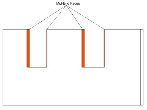
When you edit the elevation profile of a wall that spans multiple levels and create notches such as those shown below, the new vertical edges represent jambs that are referred to in Revit as mid-end faces. Other walls can form corner joins with mid-end faces. See Joining Walls to Mid-End Faces.

Wall elevation profile edited to create notches

Edited wall in 3D view
You can also create mid-end faces using the Wall Opening tool. See Cutting Rectangular Openings in Walls.