This tool examines the mechanical systems that you create in a project to verify that each system is assigned to a user-defined system, and properly connected.
Checking Duct Systems
To verify the connections for duct systems in the model, click Analyze tab Check Systems panel
![]() Check Duct Systems.
Check Duct Systems.

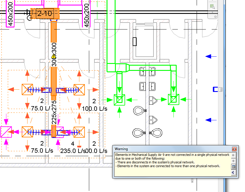
- The system is not well connected.
A system is considered not well connected when elements in the system are not connected into a single physical network. For example, a system with one or more air terminals not connected in a single network of duct is considered not well connected.
- There is a flow/demand configuration mismatch.
- There is a flow direction mismatch.

Click a warning marker to display a related warning message. In the related warning message, click the arrow buttons as needed to scroll the list of warning messages. Click ![]() Expand Warning Dialog to view the details of the warning message.
Expand Warning Dialog to view the details of the warning message.
Click ![]() Check Duct Systems again to turn off the graphical warning markers.
Check Duct Systems again to turn off the graphical warning markers.
Showing Disconnects
 Check Systems panel
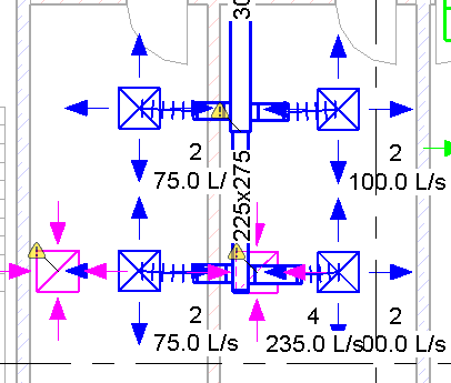
 Show Disconnects. In the Show Disconnects Options dialog, select one or more of the following:
 - Duct
- Pipe
- Cable Tray and Conduit
- Electrical
In the following example, Duct disconnect markers were selected.

Click a warning marker to display a related warning message. Click ![]() Expand Warning Dialog to view the details of the warning message.
Expand Warning Dialog to view the details of the warning message.
Click  Show Disconnects and clear the selections to turn off the disconnect markers.