You can use this method to create a sloped surface on the following types of elements:
- roofs
- soffits
- floors
- structural floors
- ceilings
- building pads
- If you are not already in sketch mode, select the element in a plan view, and click Modify | <Elements> tab
 Mode panel
 (Edit Boundary/Footprint/Sketch).
 - Click Modify | Create/Edit BoundaryDraw tab
 (Slope Arrow).
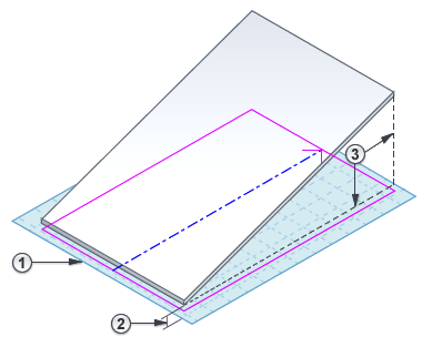
 - Draw the slope arrow in the drawing area: click once to specify its start point (tail); click again to specify its endpoint (head).
The slope arrow must start on an existing sketch line. For more examples and tips, see Slope Arrow.

- (Optional) Refine the sloped surface using one of the following methods:
Specify the height of the sloped surface at its top and bottom
- With the slope arrow selected, access the Properties palette.
- For Specify, select Height at Tail.
- Enter values for Level at Tail
 , Height Offset at Tail
  , Level at Head
  , and Height Offset at Head
  .
. 
Specify the slope (rise/run)
- With the slope arrow selected, access the Properties palette.
- For Specify, select Slope.
- Enter values for Level at Tail , Height Offset at Tail , and Slope .
- On the ribbon, click
 (Finish Edit Mode).
To see the resulting sloped surface, open a 3D view.
Related topics