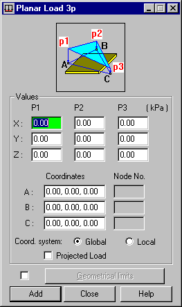
This option defines a varying load that is specified by 3 points and acts on selected planar FEs of a structure. Open the dialog by clicking ![]() in the Load Definition dialog.
in the Load Definition dialog.

This type of load acts on planar elements. It can also be distributed on bars, if it is applied to a cladding. If so, the load is distributed according to the trapezoidal and triangular method only.
A changing planar load can be defined by assigning values to 1, 2, or 3 selected points that are nodes of defined planar FEs or arbitrary points of defined coordinates.
A load distributed over an element surface can be applied to plate or shell structures. The direction of the load is defined with respect to the coordinate system axes. The planar load can be uniform or varying. For a varying load, specify the load value in 2 or 3 points. The value of a load at any point is then linearly interpolated or extrapolated on the basis of the specified values. This option is a simple and useful tool that lets you define a linearly varying planar load.
Specify the following data to define this type of load:
- Load value P along the directions of axes X, Y and Z of the coordinate system, respectively specified in points A, B, and C. A load can be defined in the global coordinate or local coordinate system of an object.
- Location of points A, B, and C. You can specify the location using either way: enter the coordinates of the points in the field, or select the node numbers of the existing planar FEs.
- If the load is projected, then it applies only to definitions in the global coordinate system.