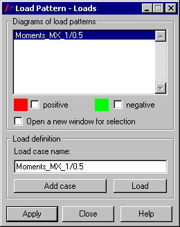
The Load Pattern - Loads dialog shown in the following image, lets you display graphically the generated influence surfaces and the definitions of new cases and loads. The dialog is displayed after clicking Generate in the Load Pattern dialog.

The dialog box has the Influence surfaces list with the previously defined surfaces.
Below, are the Positive and Negative selection fields. They are used to select the part of an influence surface to be displayed. If the Positive option has been selected, Robot displays a single color map of the influence surface in the places where its values are positive.
To display a map:
- Select one of the defined influence surfaces from the list.
- Select the Positive or Negative option.
- Click Apply.
If the Open a new window for selection option has been selected, Robot opens a new window containing a view of only a selected part of a structure model.
Depending on the settings selected in the dialog, maps with the appropriate color are drawn on the surface. Default map colors for the positive and negative parts are specified in the Preferences dialog (Tools menu > Preferences > Desktop Settings > Range: plate diagrams):
- Element: minimum values - Negative values on a map.
- Element: maximum values - Positive values on a map.
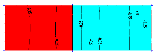
To increase map readability, isolines with descriptions (always black) are also drawn on the screen. Result values are always rescaled in such a manner so t they are contained in the interval: [-1.0, 1.0]. Range limits are determined and equal: -1.0, -0.75, -0.5, -0.25, 0.0, 0.25, 0.5, 0.75, and 1.0.
If the display of positive (or negative) values is cleared, the corresponding isolines are not displayed, either. A load pattern example is shown in the following image.

At the bottom of the dialog, in the Load definition field, there are additional buttons, which define a new load case and a planar load on a contour.
In the Load case name field, you can enter a case name. By default, the name of the currently selected influence surface is specified there.
Clicking Add case generates a new case with the specified name. (A case number is assumed automatically. It is the next free number.). Generating a case also causes the case to be specified as the current case for a given structure view.
Clicking Load button opens the Uniform Planar Load (contour) dialog. This dialog lets you define load intensity as well as the contour on which the load acts.