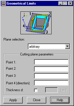
This option indicates the panel [finite element] parts on which a planar load is applied. Open the Geometrical Limits dialog by clicking Geometrical limits in the dialog that define: uniform planar loads, planar loads defined by three points, and loads with uniform and hydrostatic pressure, and thermal loads on finite elements. This option is also available in the Loads table (by clicking Limitations).

To define geometrical limitations for operating loads:
- Select a cutting plane. You can define a plane parallel to any of the 3 planes of the global coordinate system (XY, YZ, or XZ) and an arbitrary plane.
- Define a plane (for planes parallel to the global coordinate system axes, specify the coordinates of a point; for an arbitrarily oriented plane, specify the coordinates of 3 points defining a plane) and a direction (a point located on 1 side of the defined plane).
- Define a direction (point at 1 of the sides of a defined semi space). Point 4 (direction) defines a semi space in which loads exist. If Thickness d is selected; you can specify the thickness of a layer in which loads exist. The unit of thickness is based on the length of structure unit.
- Click Apply.
The load is applied to the selected part of the panel (object), which is determined by the direction (defined by the user) and the layer thickness, if defined.
Note that during the generation of a finite element mesh, loads on panels are applied to the generated elements. If geometrical limitations are defined for a load, the load is applied to the entire finite element even if it is only partially within the load limits.
In the dialog, several ways for defining geometrical limits are shown (for a XY plane and any plane).

|
Defines a plane parallel to the XY plane (axes of a global system). A half-plane is defined by specifying Point 4(direction). |

|
Defines a plane parallel to the XY plane (axes of a global system). A layer thickness is defined by specifying Thickness d. |

|
Defines an arbitrary plane. A half-plane is defined by specifying Point 4 (direction). |

|
Defines an arbitrary plane. A layer thickness is defined by specifying Thickness d. |
Data associated with geometrical limits is available in a load table as well:
- On the Values tab as a list of points, if they are defined.
- On an Edit tab as a button, showing in a different field, that opens a dialog with current data (similar to the load definition on a contour).