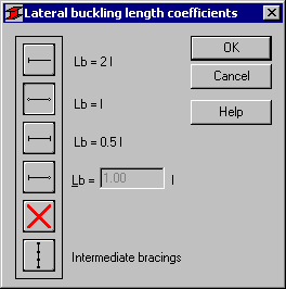
Use this option to determine the appropriate values for the distance between member sections protected against torsion (lateral buckling length). Access the option by clicking Upper flange or Lower flange in the Lateral buckling parameters field in the Member Definition - Parameters dialog (for American codes).

Due to the possibility of supporting the upper or lower flange separately and the occurrence of compressive stresses in upper or lower flange for different load cases, two lateral buckling lengths are distinguished. There is a coefficient provided, by which the base member length should be multiplied to obtain lateral buckling length. As base length, the l length is assumed. Enter a coefficient value or choose an icon with typical support case to select the coefficient automatically.
To calculate the lateral buckling coefficient properly, it is necessary to define the lateral buckling length. The dialog contains typical methods of member support which determine appropriate values of lateral buckling length coefficients.
The last icon ![]() provided in the dialog allows taking members with internal bracing (lateral stiffeners of analyzed members limiting the lateral buckling length) into account in calculations. After double-clicking this icon, the Internal bracings dialog displays and enables defining the parameters of lateral stiffeners.
provided in the dialog allows taking members with internal bracing (lateral stiffeners of analyzed members limiting the lateral buckling length) into account in calculations. After double-clicking this icon, the Internal bracings dialog displays and enables defining the parameters of lateral stiffeners.