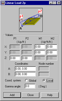
This option defines linear loads acting along a selected line defined on the planar FEs of a structure. Open the dialg by clicking ![]() in the Load Definition dialog.
in the Load Definition dialog.

This type of load acts on planar elements. It can also be distributed on bars, if it is applied to a cladding. If so, the load is distributed according to the trapezoidal and triangular method only.
The linear load is transferred onto all surface elements that are crossed by a line section connecting the beginning and end nodes (points A and B). The line defining the load does not have to coincide with the lines defined by the edges of the elements. You can define the segment in the following 2 ways:
- Enter the number of the first and last node of the structure elements
- Enter the coordinates of any 2 points at the beginning and end of a segment.
Two load types can be applied along a defined segment: the linear load p and the load of a moment distributed along a defined segment m. Enter the values of these loads in the appropriate fields.
To define this type of load, you must specify the following data:
- The appropriate P or M load values in the direction of the X, Y, or Z axis of the global or local system given in points A and B.
- The location of points A and B. This can be done in the following ways: by entering the coordinates of these points or the node numbers of the existing planar finite elements.
A load can be defined in the global coordinate or local coordinate system of an object. Also, you must decide whether a load is inclined (applies only to load definitions in the local coordinate system). If so, then you must specify the angle that the load deviates from the vertical.