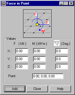
This option defines a concentrated load or a moment operating in defined points of a structure. Open the Force in Point dialog by clicking ![]() in the Load definition dialog.
in the Load definition dialog.

This type of load acts on planar elements. It can also be distributed on bars, if it is applied to a cladding. If so, the load is distributed according to the trapezoidal and triangular method only.
This dialog lets you define concentrated loads operating in user-defined points of a plate or shell structure: concentrated force F operating in directions X, Y or Z of the global coordinate system and concentrated moment M operating around axis X, Y or Z of the global coordinate system. Additionally, you can define the angles under which the concentrated force operates in a defined point of the structure. The angles are measured in relation to the global axes of the coordinate system. The positive angle is calculate counter-clockwise.
You can define the coordinates of the point where the load is applied in the Point field at the bottom of the dialog. You can define these coordinates using either method:
- Enter the coordinates of the point where the load is applied
- Click in the field and select the relevant point where the load is applied in the drawing area. The coordinates of the selected point are displayed in the Point field.
When defining an axisymmetric structure, there are 2 additional options:
-
Force intensity per circumference length unit
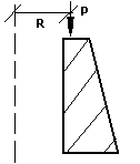
When the option Force intensity per circumference length unit is selected, the value of a uniform load p acting along the circumference of an axisymmetric structure is determined. The position of the force is defined by the R radius.
-
Force sum for the circumference
When the option Force sum for the circumference is selected, the value of the total force acting on the circumference: P = p*2pR is determined. The position of the force is defined by the R radius. Remember that the value of a uniform load p acting along the circumference of an axisymmetric structure changes depending on the value of the radius.
A force load applied to an axisymmetric structure is shown in the following image.
