Modules for Beams, Columns, Foundations and Slabs design allow you to determine the required reinforcement area and a spacing of reinforcing bars within the cross-section of a concrete structure element.
The RC Member Design module allows you to obtain a theoretical (required) area of reinforcement for selected concrete members. To access this option, do either of the following.
- Select Members - theoretical (required) reinforcement layout, in the layout group titled Design.
- Select Design > Required reinforcement of beams/columns - options > Calculations.

When creating a structure model, you define geometrical parameters of concrete beams and columns (buckling parameters, allowable values of deflection and displacements at member ends). The code parameters of concrete structure elements (steel and concrete parameters and types of reinforcing bars), are defined in a Calculation Parameters dialog.
The following codes allow you to calculate reinforcement theoretical (required) area:
- American codes ACI 318/95, ACI 318/95 (metric), ACI 318-02 and ACI 318-02 (metric)
- British code BS 8110
- Canadian code CSA A23.3-94
- French codes BAEL91 and BAEL91 mod. 99
- Eurocode 2 ENV 1992-1-1: 1991
- Eurocode 2 ENV 1992-1-1: 1991 (French NAD)
- Eurocode 2 ENV 1992-1-1: 1991 (Belgian NAD)
- Eurocode 2 ENV 1992-1-1: 1991 (Dutch NAD)
- Eurocode 2 ENV 1992-1-1: 1991 (Italian NAD)
- Eurocode 2 ENV 1992-1-1: 1991 (German NAD)
- Eurocode 2 ENV 1992-1-1: 1991 (Finnish NAD)
- Dutch code NEN 6720:1995/A3:2004
- Spanish codes: EH91, EHE98
- Italian code DM 9/1/96
- Russian code SNiP 2.03.01-84
- Romanian code STAS 10107/0-90
- Norwegian code NS 3473: 2004
- Singaporean code CP65
- Chinese code GB 50010-2002
- Japanese code AIJ 1985.
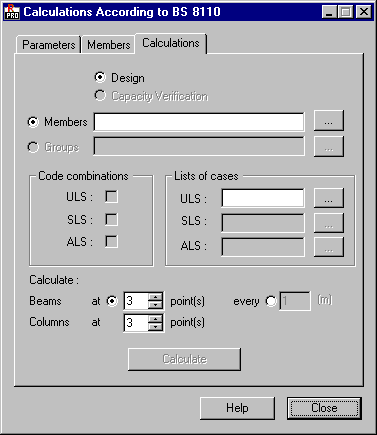
In the above dialog, the following options are displayed.
- In a Calculation type field:
- Design.
- Capacity verification (presently not available).
- In a Calculations for field elements taken into consideration in calculations:
- Members.
- Member groups (presently not available).
Lists of elements taken into consideration during calculations are defined in three ways:
- Manually entering the member numbers in an appropriate edit field.
- Starting a selection dialog box with a '...' button.
- Indicating the elements on the screen with a structure view.
Design cases:
- Code combinations.
- Lists of cases for each of analyzed limit states.
A set of active fields is different for different codes. Choice fields for code combinations are active only when such calculations have been generated before. A list of cases can be entered in the appropriate field or in a Selection dialog starting with the '...' button.
Number of calculation points for beams can be defined in two ways:
- By defining calculation points at beam length (min. = 3, max. = 100), giving at what length unit the calculations should be performed. The beginning point is a result of accepted options in the Concrete beam definition (Span length and support width) dialog.
- Capabilities and limits of the module used for calculation of theoretical (required) reinforcement area for concrete members and depend on a chosen concrete code.
See also:
Interpretation of calculation results for RC member theoretical (required) reinforcement.