In this model, we determine the displacement, stress, and safety factor of a pin joint often used in hydraulic applications.
Before you begin, please watch this short video that demonstrates the steps of the tutorial:
To start, download the model archive by clicking here. Save this file to a folder on your computer, and unzip the contents.
Open the Model
- Locate the file Pin_Joint_Setup.ach using your Windows file browser and double-click the file to launch Simulation Mechanical 360.
- You will be prompted to select the folder where you want the extracted model files to be located. The default location is the folder where the archive file resides.
- Click OK. The model appears in the FEA Editor environment, and you should see this:
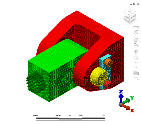
The model has already been meshed and set up with the following material, load, and constraints:
- Mesh size: 0.125 in
- Material: Steel (ASTM - A36 and AISI 4130)
- Load: 1,500 pound axial force on the end of the rod eye (indicated by green arrows).
- Constraints: Fixed constraints on the four bolt holes on the back of the clevis.
Analyze the Model
We are now ready to analyze the model.- Click
 Analysis
  Analysis Run Simulation.
 - The analysis will run and the results will be downloaded from the cloud to your computer and displayed within the Results environment.
- You will also be sent an email message notifying you that the analysis has completed (assuming you completed the instructions under Cloud Notification Setup on the Introduction page.) This feature is useful for large or complex analyses that may complete while you are not at the analysis workstation.
Review the Results
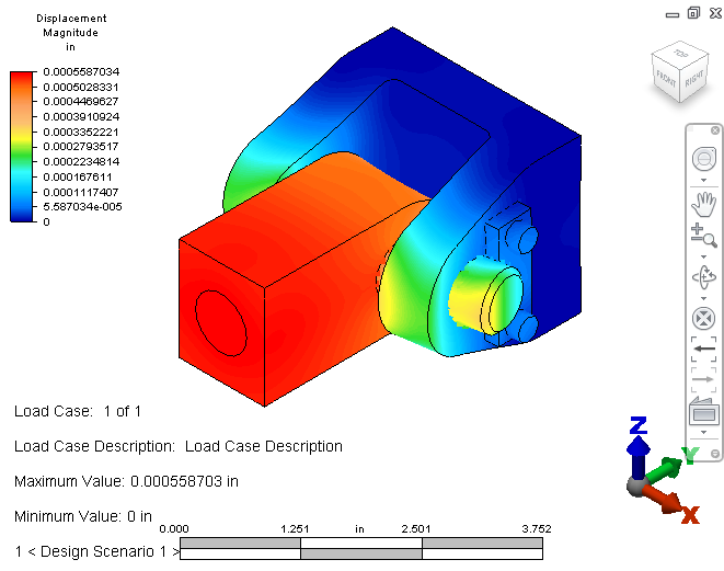
We begin by reviewing the displacement results. As you can see, the displacement magnitude values appear by default in the Results environment.
- The displacement results should look like this:
- Click
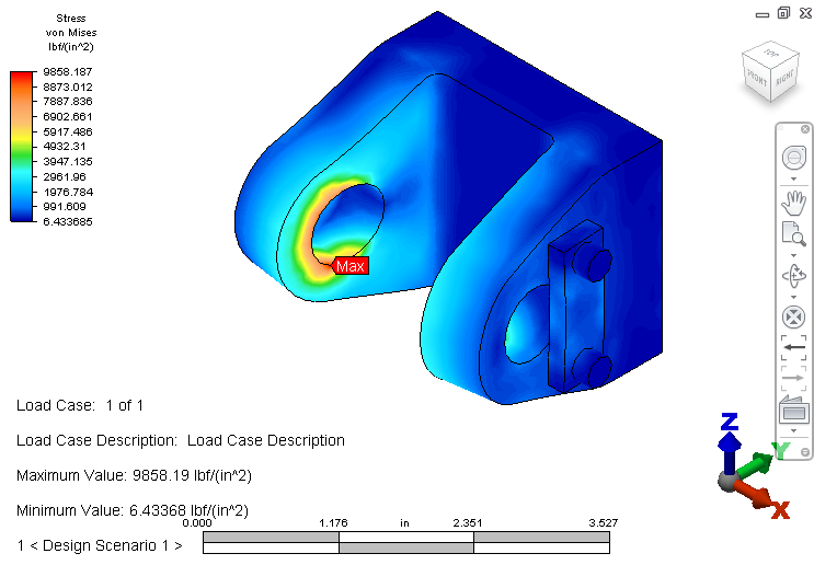
 Results Contours Stress von Mises.
 - To locate the maximum stress, click
 Results Inquire Probes Maximum.
We need to hide the rod eye and the pin parts to view where the maximum stress occurs.
- Expand the Parts branch of the Browser, right click on the Rod_Eye part, and click Visibility to uncheck it. Right click on the Pin part, and click Visibility to uncheck it as well.
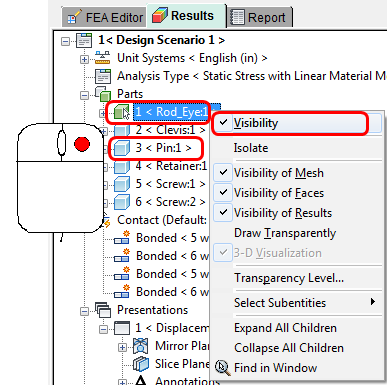
You should see this:
Let's look at the safety factor based on the yield strength of ASTM - A36 steel (36,000 psi). We'll modify the legend to clarify the view.
- Click
 Results Contours Stress Safety Factor. The allowable stress is automatically set to the material yield strength.
 - Click
 Results Contours Settings Legend Properties.
 - Access the Range Settings tab of the Plot Settings dialog box.
- Uncheck Automatically calculate value range.
- Enter 1 in the Low field, and 10 in the High field.
- Click OK. Note: The range colors are reversed for safety factor results. (Red represents the minimum value and blue the maximum.)
- Click Results Inquire Probes Maximum to deactivate the maximum result probe.
- Click
 Results Inquire Probes Minimum to mark the point on the model with the minimum safety factor result. You should see this:
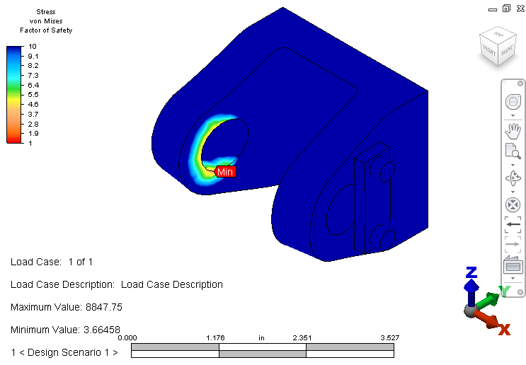
- Click
Good job! This completes the Pin Joint model.
Next Steps
In this exercise, the model was already set up. If you want to go through the steps yourself and learn more about linear static stress analyses in Autodesk® Simulation Mechanical, click here.
To explore a Mechanical Event Simulation or learn about Autodesk Simulation Mechanical resources, click here.