Previous: Chapter 11 | Next: Chapter 12
This exercise teaches how to define the analysis parameters, to start the analysis, and to verify it is running correctly.
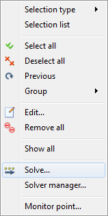
1. Right click off the model, and click Solve…
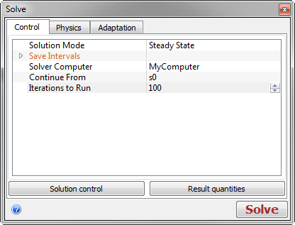
2. On the Control tab, Iterations to Run = 100.
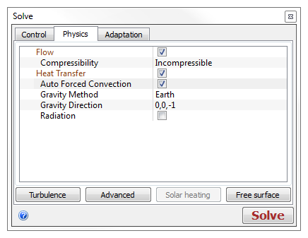
3. On the Physics tab, enable Heat Transfer and Auto Forced Convection. Click Solve.
4. When startup processing is complete and the analysis has started, the solution progress is plotted on the Output Bar of the Convergence Monitor:

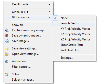
5. When this graph appears, right click off the model, expand Global Vector, and click Velocity Vector.
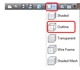
6. Change the view to Outline and confirm that flow is entering through the front of the cabin and exiting at the rear.
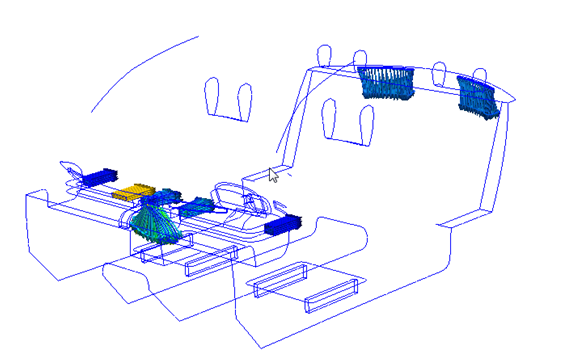
7. If the vectors do not appear as shown above, right click, and select Solve.... Click Stop in the Solve dialog. Review material assignments, boundary conditions and flow directions, and mesh settings, and fix as necessary.
8. Run the analysis to completion before proceeding to Chapter 12.
End of Exercise