In this video, we describe the basics of the Simulation CFD process.
Video Notes
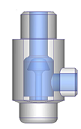
1. The CAD Model
It all starts with geometry.
If you built the model in a CAD system, it probably contains solid parts. To use it with Simulation CFD, it needs one or more fluid parts. There are several ways to create a fluid part:
- Create it in CAD.
- Build volumes that "cap" the openings to make the volume "water tight."
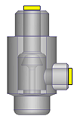
- Use the Fluid Part tool in Autodesk® Inventor Fusion.
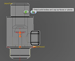
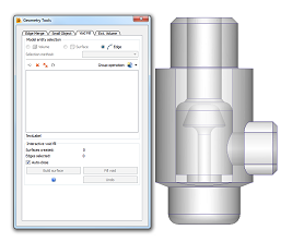
- Use the Void Fill tool in Simulation CFD.
Launch the model either directly from the CAD system or by opening the model file in Simulation CFD.
To learn more about the CAD model for simulation, click here.
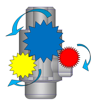
2. Enter What You Know
In this step, you describe the physical characteristics of the system.
A. Materials
Setup > Setup Tasks > Materials

Define what flows through the device, air, water, etc., as well as the solid parts.
To learn more about materials, click here.
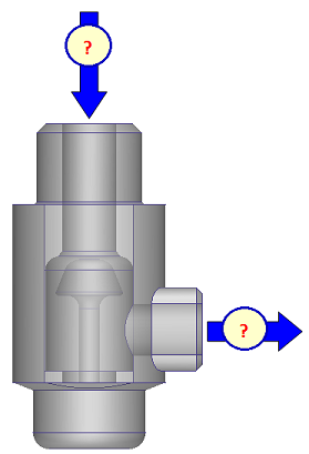
B. Boundary Conditions
Setup > Setup Tasks > Boundary Conditions

Describe the flow at the openings and heat transfer wherever heat enters or leaves the system.
To learn more about boundary conditions, click here.
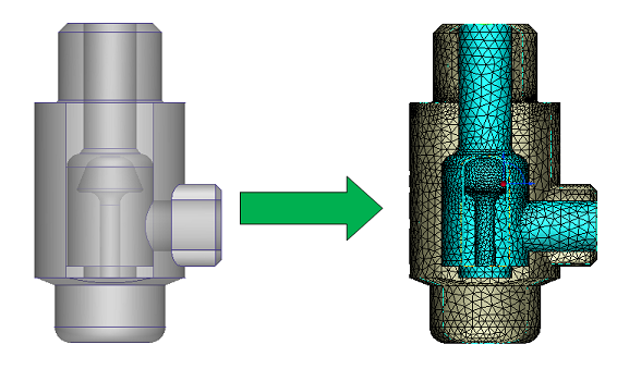
C. Mesh Sizing
Setup > Setup Tasks > Mesh Sizing

This is how we convert the geometry model into a simulation model.
The process is almost entirely automatic. Simply click this button:

To learn more about meshing, click here.
3. Run the Simulation
Setup > Simulation > Solve

After you have described the model, you are ready to solve.
Simulation CFD uses an iterative calculation process. This means that the solver computes a solution in many small steps (iterations). Throughout these steps the solution evolves. After some number of iterations, the solution does not change anymore, and is considered "converged."
To learn more about solving the simulation, click here.
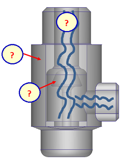
4. Learn what you didn't know (visualize the results)
Results > Result Tasks
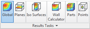
Here is where you learn how the flow and heat move within your model. Simulation CFD has some great tools for visualizing and extracting results.
The type of result you need largely depends on the type of application:
Valves and other flow control devices
Flow control simulations usually show how the fluid flows through the device as well as either the pressure drop or the flow rate.
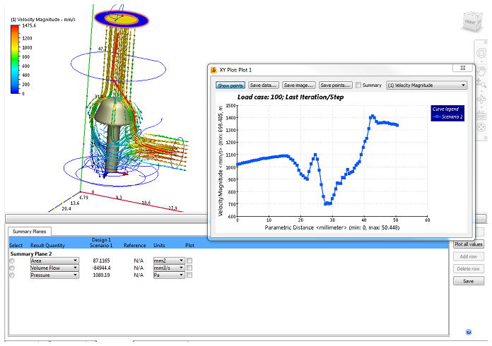
To practice with a flow control model, click here.
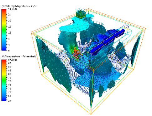
Electronics Cooling
Electronic cooling simulations typically show component temperatures and how cooling air flows through the enclosure.
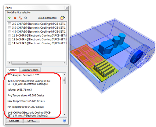
To practice with an electronics cooling model, click here.
AEC
AEC simulations show how the ventilation air moves in relation to the occupant and if the occupant is comfortable.
To practice with an AEC model, click here.
To learn more about visualizing results, click here.
5. Iterate and Compare
A single scenario is just the first step. In many cases, you may want to try several design alternatives.
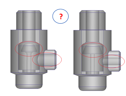
Simulation CFD makes it easy to transfer settings from one model to another and run variations in the same design study.
When finished, you can compare the results in the Decision Center.

The Decision Center provides several ways to compare simulation results from multiple simulations:
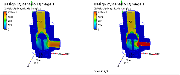
To learn more about running and comparing Design results, click here.
Next Step
The next video is about the Basic Model Interactions.
Alternatively, you can return to the Quick Start home page to watch a different video, do a tutorial, or start applying what you've learned.