Example Mesh Distributions
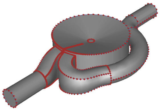
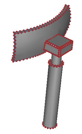
The mesh distributions on each of these cases were computed automatically by clicking Autosize. The dots on the model edges (Mesh Seeds) indicate where the nodes will be constructed. The location and spacing of the dots does not change if the Selection Mode is changed.
|

|
|
|

|
|
Surfaces and edges with high curvature are meshed finer, and those with little or no curvature are meshed coarser. Edges that are close to other edges are assigned smaller element sizes which can vary along the span of the edge.
If there are edges that do not have seeds, the surfaces may not be meshable. This is can occur on extremely thin surfaces or due to some other geometric flaw. This should be corrected in the CAD system prior to running the simulation.
To toggle the display of the mesh seeds, click View (tab) > Appearance (drop-down menu) > Mesh Seeds.
Automatic Sizing Refinement Preview
To Preview the effect of Automatic Sizing Refinement
This is enabled after Surface refinement is enabled from the Mesh Sizes quick edit dialog.
- Press and hold the keyboard Shift key.
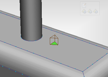
- Hover the mouse over surfaces and near gaps.
A small prism indicates the element size:
Mesh Preview
To view the mesh prior to generating the mesh:
- Select surfaces or volumes.
- Right click, and select Preview.
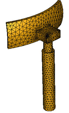
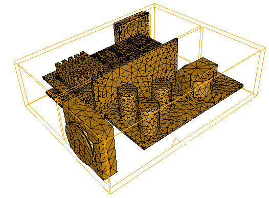
The mesh faces appear on the selected surfaces. Note that if volumes are selected, the element faces appear only on the surfaces of the selected volumes.
To preview the mesh on a single surface (or surfaces of a single volume):
- Right click on the surface or volume.
- Select Preview.
If a volume is selected, the preview appears on the surface of the volume.
To remove the previewed element faces:
- Select the surfaces or volumes that are displayed with a previewed mesh.
- Right click, and select Clear.
If the mesh distribution needs to be updated after making certain changes, the preview is not available.