What should the CAD model look like?
An effective simulation starts with good CAD techniques both in terms of model integrity and proper creation of the flow region. The first step is to design your CAD model for the flow analysis. This means modeling the flow geometry and optimizing the model for simulation.
Optimizing the Model for Simulation
The Problem
- Production-level geometry can contain gaps, interferences, fasteners, and very small features.
- These features are often necessary for manufacturing, but can add unnecessary complexity for simulation.
The Solution
- To save time and computer resources, eliminate these features if they are too small to affect the results of the simulation.
- For large assemblies, consider analyzing only critical portions of the design. This can accelerate the analysis process.
- In some cases, it is faster to create a new, simpler version of your design to focus on the key areas of study.
Steps you should always take to prepare the geometry:
- Eliminate gaps that prevent void filling. These include clearances between parts, sheet metal reliefs, and fastener holes.
- Eliminate fasteners that do not impact flow or heat transfer.
- Reduce very large assemblies to include only vital components.
- Eliminate interferences. Examples include press-fits and improper mates.
Steps to help reduce the analysis time:
- Eliminate very small features that do not affect the analysis results. These include:
- Small fillets
- Chamfers
- Very small parts
- Fill small gaps in the flow region that are not important.
Examples
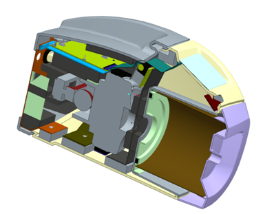
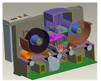
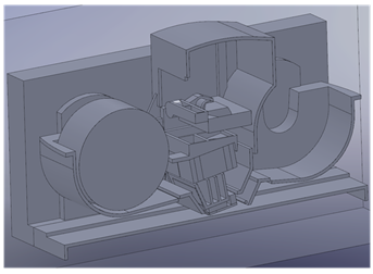
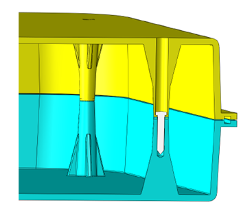
These examples show geometric modifications that prepare production geometry for simulation. By removing superfluous features such as interferences, gaps, fasteners, and small details, we greatly reduce the simulation time and complexity of these models.
|
Production |
Simulation |
|
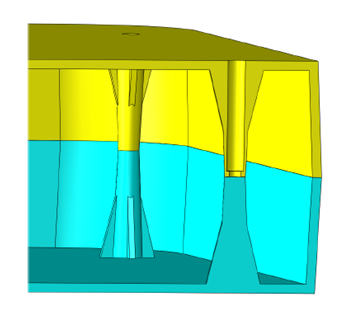
Note: We removed the interferences, fasteners, small gaps and the extremely small fillets.
|
|
|
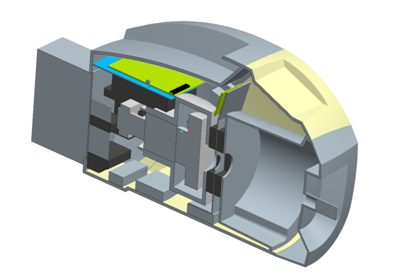
Note: In addition to removing the interferences, fasteners, small gaps and the extremely small fillets, we removed several components that are not important to the analysis.
|
|
|
Note: In addition to removing the interferences, fasteners, small gaps and the extremely small fillets, we removed several components that are not important to the analysis.
|
