Use the Autodesk® Simulation CFD Viewer to:
- Collaborate across multiple engineering workgroups
- Present and share Autodesk© Simulation CFD graphical results
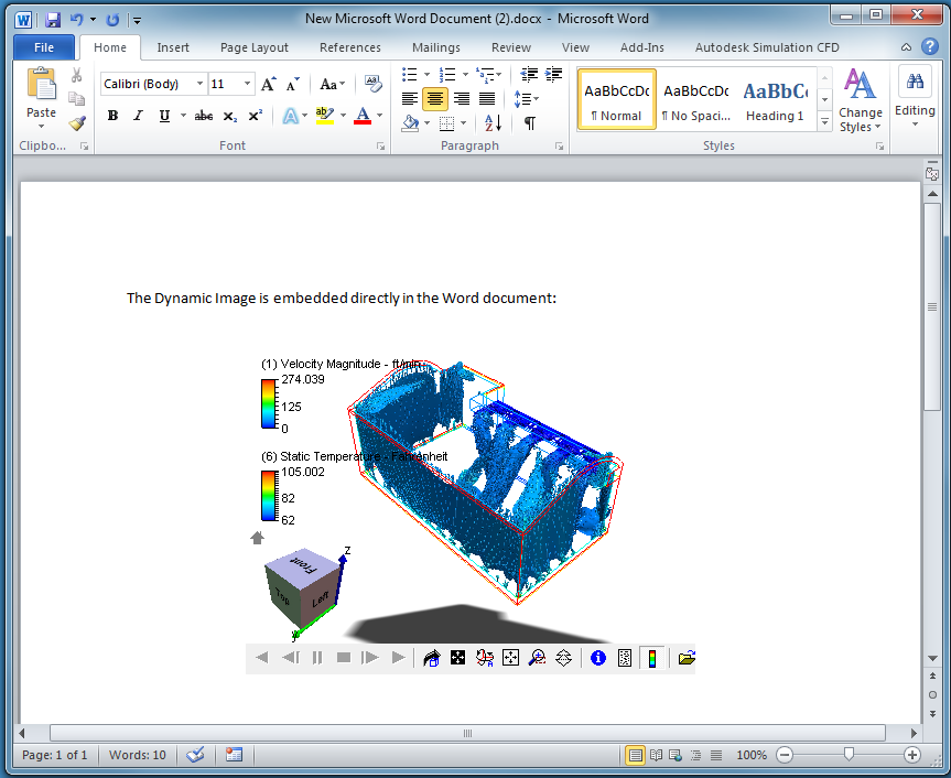
The Autodesk® Simulation CFD Viewer reads Dynamic Images (".vtfx"), which contain the model geometry, results, display attributes, and animation settings. They are fully navigable, so unlike static images, they allow direct interaction for a deeper understanding of the results.
To save a Dynamic Image, click Results (tab) > Image (panel) > Dynamic Image.
Main Window
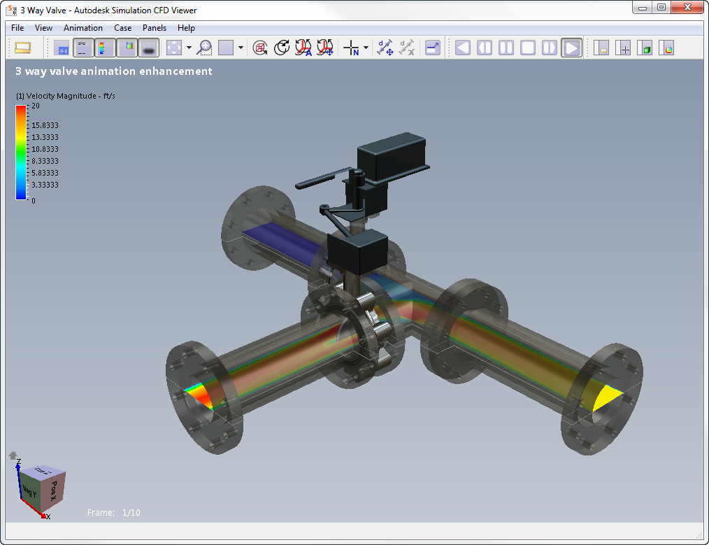
The Autodesk® Simulation CFD Viewer is shown with a results set loaded:
Toolbar Functions
|
File Open
|
Open Dynamic Images (VTF and VTFx) created in Autodesk® Simulation CFD. |
|
InfoBox On/Off
|
Toggle the display of the Result Info box in the lower right corner of the graphics window. This shows the date, the active scalar and vector quantities. |
|
Step Info On/Off
|
Toggle display of time step and load case information. This is shown in the lower left corner of the Graphics window. |
|
Color Legend On/Off
|
Toggle display of all legends. |
|
Navigation Cube On/Off
|
Toggle display of the Navigation Tool. 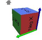 |
|
Drop Shadow On/Off
|
Toggle display of the shadow visual effect below the model. |
|
Modify
|
Reset View: Restore the original view of the image Frame Model: Display the model at its maximum size in the viewport |
|
Rubberband Zoom
|
To zoom to a region:
|
|
Viewports
|
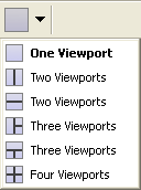
Select the number of viewports and their initial placement. |
|
Move as Outline
|
Converts the model to outline while navigating. Use this setting for very large models on computers with slower graphics hardware. |
|
Synchronous Navigation
|
Causes the mouse movement in all viewports to be the same This is useful when comparing designs and scenarios in multiple viewports. |
|
Automatic Rotation Point
|
Click to enable automatic computation of an optimal rotation point based on the geometry. The default center of rotation is the origin. |
|
Set Rotation Point
|
Set a rotation point by picking a node in the model |
|
Selection
|
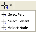
Select Part: Toggle to select a part and probe values on the part Select Element: Toggle to select an element and probe values on the element Select Node: Toggle to select a node and probe value from the node |
|
Distance Measurement
|
Measure the distance between two nodes on results objects (cutting planes, iso surface, etc.). |
|
Delete Distance Measurement
|
Clear all distance measurements |
|
Full Screen
|
Display in full screen mode |
|
Animation Control
|
Use the animation control buttons to pause, play, and single step through the animations to inspect individual steps |
|
Case Selection 
|
Every case that is included in the Study View (VTFx) file is listed in this drop menu. Use the arrows to select the case to view. |
|
Case Panel
|
The Case Panel lists information about each case (scenario from Autodesk® Simulation CFD). To show a case, drag and drop its thumbnail in the Table of Cases list into a viewport. |
|
Selection Panel
|
Probed results are displayed in the Selection Panel. |
|
Settings Panel
|
Use the Settings Panel to manipulate visibility and drawing modes of parts and element sets. Visiblity options include visibility, shaded, and outline. |
|
Results Panel
|
Use the Results Panel to control the display of results and legend range and appearance. |
Model Navigation
| Zoom | Ctrl + LMB |
| Rotate | Ctrl + MMB |
| Pan | Ctrl + RMB |
Microsoft® Office Add-Ins
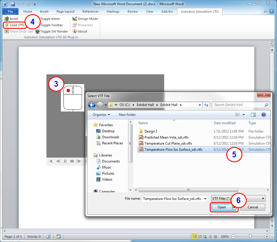
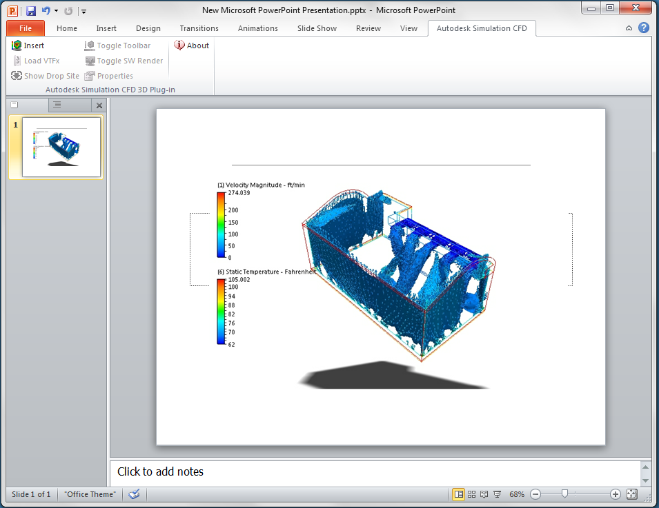
The Simulation CFD 3D Viewer has connections to Microsoft® PowerPoint and Microsoft® Word. These enable Dynamic Images to be a part of your Office presentations and documents.
PowerPoint
Before adding a Dynamic Image for the first time, add the CFD Viewer AddIn:
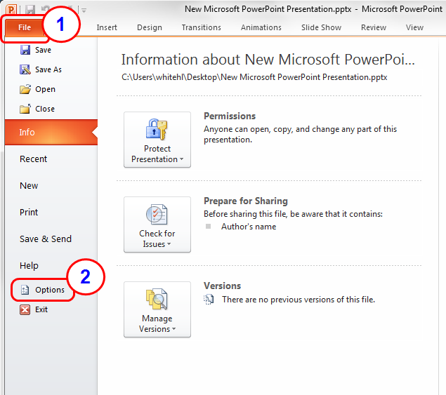
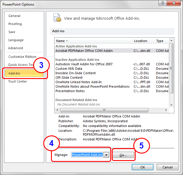
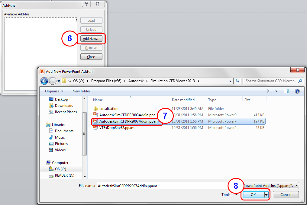
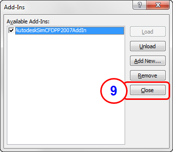
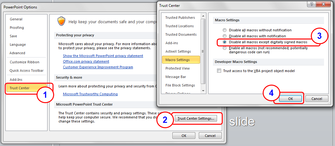
If the button does not appear, reduce the PowerPoint security settings:
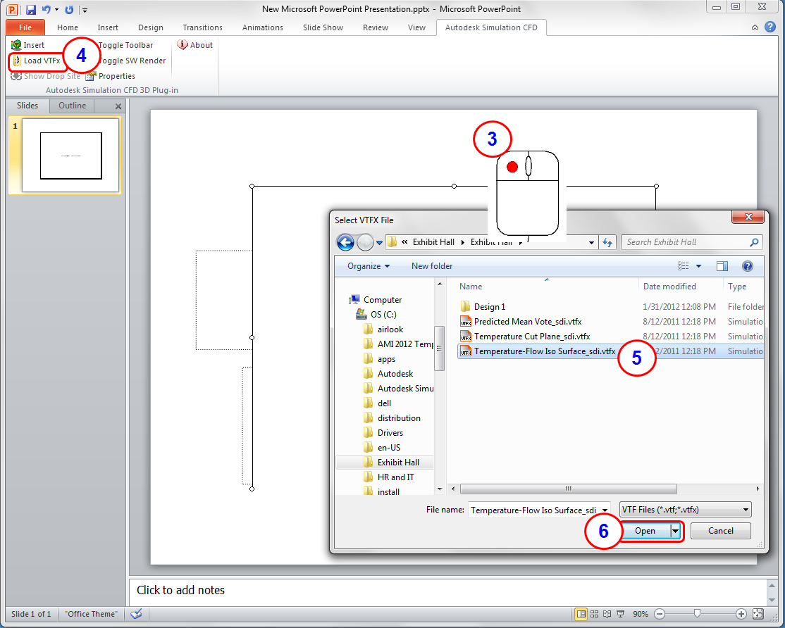
To add a Dynamic Image:

Word
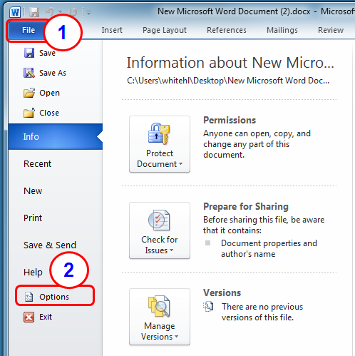
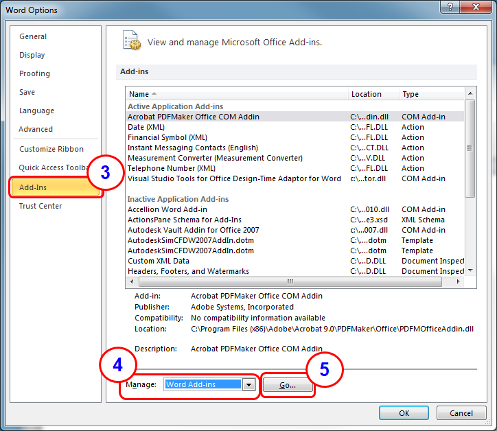
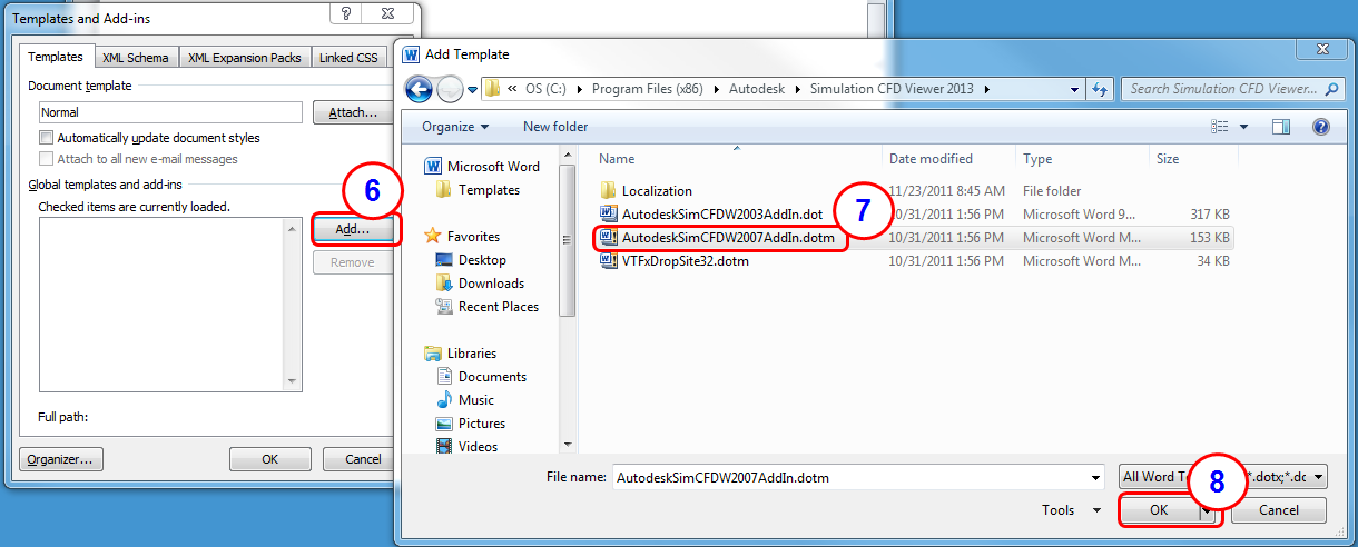
Before adding a Dynamic Image for the first time, add the CFD Viewer AddIn:

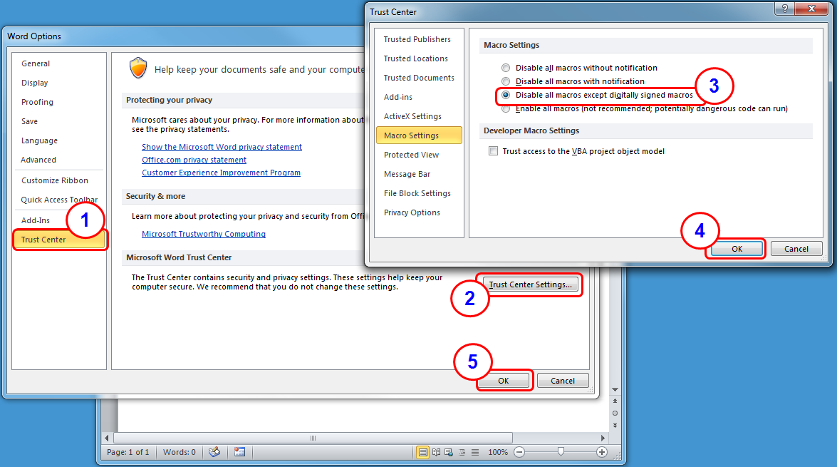
If the button does not appear, reduce the Word security settings:
To add a Dynamic Image:

