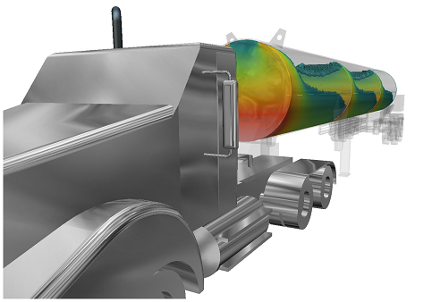
Free Surface
Autodesk Simulation CFD 2014 adds the ability to dynamically simulate the interface between liquids and gases. This ability is essential for modeling many flows that occur in nature, as well as in a wide range of engineering applications.
Examples of Free Surface Applications
You can use Free Surface to simulate many different applications. Here are several examples:
-
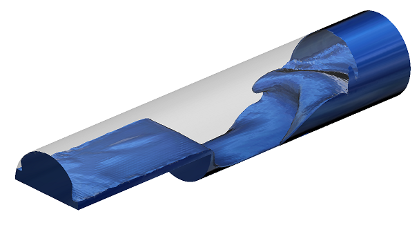
Liquid movement within tanks
- Sloshing: How a liquid moves in a partially filled container.
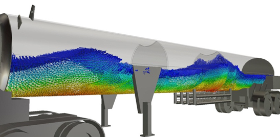
- Agitation: How a liquid behaves in a tank with submerged or partially submerged agitators, baffles, and/or multiple inlets and outlets, or by tank motion. (Examples of tank motion include seismic effects and mobile tanks in transit.)
- Mixing: Concentration of different liquid species.
-
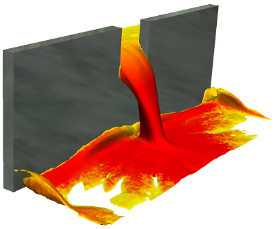
Water Transport & Infrastructure
- Civil structures: Dams, culverts, spillways, and weirs.
- Valves: Open channel flow.
- Water Tanks: Fill/draw cycles or continuous inflow and outflow.
Basic Free Surface Setup
When constructing and setting up the model, consider the model in terms of the liquid. Be sure to include the liquid regions in the CAD model. Assign materials and boundary conditions based only on the liquid. Consider regions occupied by gas (air) to be void of liquid.
- Assign a liquid material to the parts that contain or will contain fluid. Do not assign a gas material to a part if it currently contains or will contain liquid. Simulation CFD does not allow multiple materials to be assigned to the same part.
- To indicate where the liquid enters the domain, specify a flow boundary condition (velocity, volumetric flow rate).
- If the domain is full or partially full at time = 0, specify an HOF initial condition to indicate the initial location of the liquid. Create the geometry such that a distinct volume exists for the initial liquid level.
- If the tank is empty at time = 0, assign the liquid material to the volume, but do not assign an HOF initial condition. The liquid enters the domain because of the specified flow boundary conditions.
- Mesh all fluid parts and parts that the liquid will occupy, even partially. The mesh requirement for free surface simulations is high. Assign a fine mesh at the liquid-gas interface.
Simulation CFD runs free surface simulations as transient, and automatically computes the time step.
To enable Free Surface:
- Open the Solve dialog box (Setup (tab) > Simulation (panel) > Solve).
- Click Free surface on the Physics tab.
- On the Free Surface dialog, check Enable free surface.
- Specify the acceleration forces acting on the liquid by setting the Gravity vector. You can also specify more acceleration components with the Acceleration settings. These commands are useful for simulating body forces such as in a moving tank.
To visualize the resultant liquid volume:
- Right click the model, and select Free Surface.
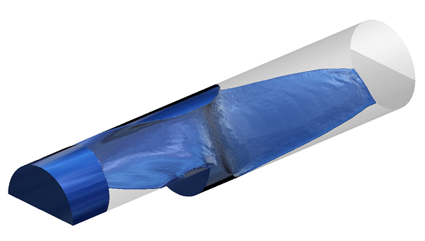
- Display the VOF result quantity. A value of 0.5 indicates the liquid-gas boundary.
- To see the liquid movement, display VOF as an iso surface with vectors:
To learn more about free surface, click here.
Advanced Turbulence Models
To improve accuracy and reduce mesh-dependence for certain types of simulations, Simulation CFD 2014 contains several new turbulence models:
-
SST k-omega
- We recommend this turbulence model for flows with separation or detachment as well as for adverse pressure gradients.
- Additionally, this model is robust across a wide range of flow types.
- To use this model effectively, use a fine mesh in the boundary layer region. You can add up to ten layers with the Mesh Enhancement dialog box.
-
Detached Eddy Simulation (SST k-omega DES)
- Hybrid between SST k-omega and large eddy simulation (LES).
- Produces accurate results for separated, high Reynolds external aerodynamics flow applications.
- This model is fairly computationally intensive and is sensitive to mesh distribution. It works best with a uniform mesh distribution.
-
Scale Adaptive Simulation (SST k-omega SAS)
- We recommend this model for transient (time-dependent) flow applications.
- To use this model effectively, define a fine mesh in the boundary layer region. You can add up to ten layers with the Mesh Enhancement dialog box.
To enable these models:
- Open the Solve dialog box (Setup (tab) > Simulation (panel) > Solve).
- Click Turbulence on the Physics tab.
- Select from the Turb. model menu.
To learn more about these turbulence models, click here.
Distributed Resistance Accuracy Improvements
In response to user feedback, the distributed resistance formulation in Simulation CFD 2014 is improved to better simulate these two situations:
- Radially shaped resistance regions (including large variations in directional K values and regions not aligned with the Cartesian axes)
- Planar regions not aligned with a Cartesian axis
In both cases, the formulation more accurately predicts the pressure drop and velocity distribution, especially for low values of K. The formulation changes in Simulation CFD 2014 produce higher accuracy results with greater consistency than previous versions.
There are no changes to the user interface or workflow to support these improvements.
Temperature Results Improvements in PCB Materials
Simulation CFD 2014 computes the temperature distribution in Printed Circuit Board (PCB) materials not aligned with the Cartesian axes with greater accuracy.
Removed Functionality
Simulation CFD 2014 no longer contains the two Quick Convection heat transfer models.