Analysis Characteristics
- Transient
- Three Dimensional Flow
- Turbulent Flow
- Rotating Flow
- Centrifugal Pump
- Pump Volute
Reference
Miner,S.M., “Potential Flow Analysis Of A Centrifugal Pump: Comparison Of Finite Element Calculation And Laser Velocimeter Measurement”, Ph.D. Dissertation, University of Virginia, 1988
Problem Description
The reference contains flow data from a laboratory scale pump obtained using laser velocimetry.
In this case, we compare the flow rate calculated in Autodesk Simulation CFD with the measured operating point. We will assign a pressure head for the pump, predict the flow rate, and compare this flow rate to the experimentally determined head-capacity curve.
Geometry and Boundary Conditions

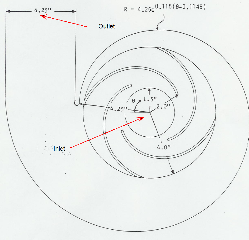
The impeller is a shrouded 4 bladed design with 16° log spiral blades. The inlet radius is 1.5 inches, the discharge radius is 4.0 inches and the leading edges of the blades are at a radius of 2.0 inches. The volute is a log spiral design. The volute angle of 83° was chosen to match the flow at the discharge of the impeller. The channel width of the impeller and volute regions is 0.97 inches.
Results
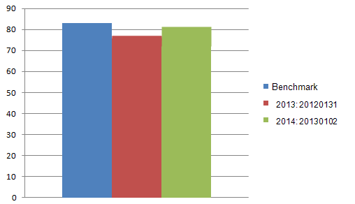
| Benchmark | 2013: Build 20120131 | % Error | 2014: Build 20130102 | % Error | |
| Flow Rate | 83 gpm | 75.91 | 8.53 | 81.79 | 1.45 |
