The Solar model works in conjunction with the radiation model, and supports radiative heat transfer through transparent media and simulates the effects of shadowing on other objects.
The Solar Heating dialog allows for specification of specific geographical locations as well as input of latitude and longitude. The date, time, compass direction, and object orientation relative to the sky are also specified.
A full report of the radiative energy balance similar to the reports shown in the previous section is provided during and after the analysis.
Geometry
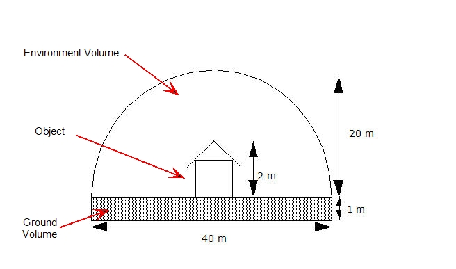
To properly compute the solar heating of an object, it must be fully enclosed by a larger volume that represents the environment. A volume representing the ground can also be included in the model, but is not required. The purpose of both regions (environment and ground) is to properly simulate the effects of reflected and emitted radiative heat transfer between the object and its surroundings. These two elements in a solar model allow for proper simulation of the indirect solar flux to and from the ground and the radiative energy loss and/or gain to the sky.
The ground volume should be approximately a meter thick. The thickness is significant only if diurnal heating over several days is studied, in which case it is necessary to compute the thermal inertia of the ground. The ground part should be approximately 20 times wider than the studied object.
The shape of the environment volume is not critical, and a hemisphere or cube are the most convenient choices. The environment volume should extend at least 10 times the height of the objects in the analysis model. A smaller environment can be used, but if natural convection is analyzed, a small volume will influence and potentially complicate the buoyancy-induced flow. Also, if diurnal heating is analyzed, a cold sky temperature that is too close to the object will artificially cool the object through conduction.

Note that only three dimensional geometry is supported for solar analyses because the motion of the sun is a function of its altitude and its East-West (azimuth angle) orientation. Since the solar energy flux is a function of three dimensional space, Autodesk Simulation CFD does not convert this energy into an equivalent energy load in two dimensional models. For example, for a model that is axisymmetric in the Y axis, solar input only exists on one side of this object. This conflicts with the condition of symmetry about the Y axis because the solar heating is non-symmetric by its very nature.
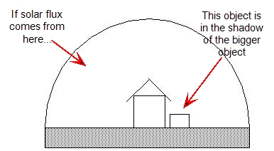
The relative locations of objects in an analysis model are important because shadowing is computed by the Solar Heating model. When an object blocks solar flux (either partially or completely) from hitting another object, that blocked object is shadowed. Such an object is still subject to receiving indirect radiant heat flux from the sky, the ground, and surrounding objects.

Analysis Settings
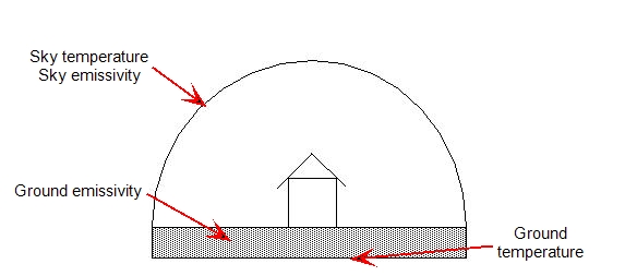
Temperature boundary conditions and emissivity values should be specified for both the ground and sky.

The ground temperature depends on the location on the Earth, and should be specified on the external surface of the ground volume. The emissivity of the ground should be specified as a property of the ground material. This value depends on the type of material. Grass surfaces, for example, may have an emissivity of about 0.3, while asphalt may have an emissivity of about 0.8. White surfaces such as an airport tarmac, are highly reflective, and would tend to have very low emissivity values.
Apply the sky radiation temperature to the exterior surface of the dome. This temperature typically falls within a narrow range, roughly between 0 and 30 °C. Note that this is not the air temperature. During the day, the sky temperature is nearly the ambient temperature. At night, however, the sky temperature falls to about 0 C. On very cloudy nights in warm climates, the sky temperature may be warmer than this. On clear nights in cold climates, the sky temperature can be as cold as -15 C.
The amount of cloud cover and the amount of ambient light affect the amount of radiant energy that is reflected off the sky and back to earth (the albedo). Use the value of emissivity specified on air to control the emissivity of the sky (and hence the reflectivity). The emissivity controls the amount of reflected energy: (reflection = 1-emissivity).
- A clear sky with little or no cloud cover has a higher emissivity value (and hence lower reflectivity) than a cloudy sky.
- At night, a clear sky might have an emissivity as high as 1, but because of the low night-time sky temperature, it acts as an emitter that is cold, so little heat is emitted back to the object and ground.
- A cloudy night sky will have a lower emissivity (higher reflection), so the clouds reflect the radiation emission from the ground, and will limit the heat loss of the ground.
To study diurnal heating, specify the sky temperature as a transient boundary condition, and assign the emissivity of the air (which is automatically assigned to the exterior surface of the environment volume) as a function of temperature. During the day, high sky temperature corresponds to lower emissivity. During the night, low sky temperature corresponds to higher emissivity values.
You can incorporate transparent objects, such as windows, into solar heating analyses. Assign a Transmissivity property value in the Material Editor. Because all parts are internal to a solar heating analysis, you should not use the Transparent boundary condition in a solar heating model. This boundary condition prescribes an external temperature on objects that are on the exterior of a model, so it is not appropriate for objects in the interior of a solar analysis. The solar heating load does not propagate through transparent objects to creating 'hot spots' on the ground or floor. Instead, the energy passes through the object as defined by the Transmissivity property, and is then evenly emitted from the opposite surface
Running a Solar Heating Analysis
There are two ways to run a solar heating analysis: as steady-state or as transient. When run as steady state, the time specified on the Solar Heating dialog does not change throughout the calculation. This is ideal for computing the “worst case” solar heat loading on an object during the heat of the day. Also, this regime is useful for determining seasonal variations in the peak solar loading.
To study the variation of solar loading over a longer period of time (either within a single day or over multiple days and nights), a solar heating model can be run transient. The time and date specified on the Solar Heating dialog are that at the beginning of the simulation. If analyzing diurnal heating over a long period of time (several days, for example), we have found that it is convenient to divide a day into 100 time steps. This is a time step size of 864 seconds.
If buoyancy effects are to be studied, then a significantly smaller time step will be necessary.
When running a diurnal solar analysis, it will likely be important to vary the sky temperature with time so that the appropriate value is used during day and night. Likewise, define the sky emissivity to be temperature-dependent to properly represent the reflective effects of ambient light and cloud cover.
The two result quantities that provide the most insight into the effects of solar loading are Temperature and Solar Heat Flux. Solar heat flux is enabled automatically for Solar applications, and is included in the Global Scalar Result list.
Radiation Energy Balance with Solar Heating
A complete reporting of the radiation energy balance is also provided in the Summary file when running Solar Heating. Below is a sample of such a report. Comments about the meaning of certain items are written below the line and are preceded by a “>>>>” symbol.
Simulation Time 1.728000e+003 seconds, year = 2006, month = 2, day = 1 hour = 12 minute = 25 second = 5
L2 Norm of residual before solve = 1.06209e-003
Radiosity Solution has converged
Iter=10 ResNorm = 6.36236E-014
CPU time to solve radiosity matrix = 4
Radiation heat balance = 4.1933e-010/ 86.259 = 4.8613e-010%
Radiation Heat Loads by Part ID:
| ID |
Radiation Heat Load (Watts) |
Area (mm^2) |
Surface Temperature (K) |
Emissivity | Transmissivity |
| 1 | 0.1875/ 0 solar | 5959.3 | 298.43 | 0.7 | 0 |
| 2 | 0.19787/ 0 solar | 5959.3 | 298.83 | 0.7 | 0 |
| 3 | 12.858/ 14.379 solar | 1.56e+005 | 303.46 | 0.2 | 0.6 |
| 4 | 0.57946/ 0.51806 solar | 5959.3 | 300.24 | 0.7 | 0 |
| 5 | 0.78074/ 0.69285 solar | 5959.3 | 301.29 | 0.7 | 0 |
| 6 | 71.656/ 70.67 solar | 1.21e+005 | 303.73 | 0.94 | 0 |
| Total | 86.259/ 86.259 | 3.01e+005 | 303.27 |
>>>> Part 3 is picking up 14.379 Watts through incoming solar flux, but its net increase is only 12.858. This means that this part lost about 1.5 Watts to its surroundings. Part 6, conversely, has a slightly higher net influx than it received from solar. This means that it picked up additional radiant energy from its surroundings. Note that the total solar heat load = total radiation heat load, indicating a good radiation energy balance.
Related Topics