It's hot outside for our summer design day, and we're going to model the external conditions with an applied U value (also known as a convection condition or film coefficient). Because this scenario simulates a design day, we'll use a value that simulates air movement only by natural convection and a high temperature outside of the exhibit hall. (Basically, it's hot and there's no shade!)
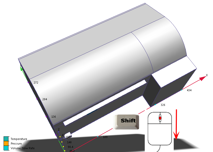
1. Rotate the model so you can see the surfaces of the roof.
(To rotate, hold the Shift key, press the middle mouse button, and move the mouse.)
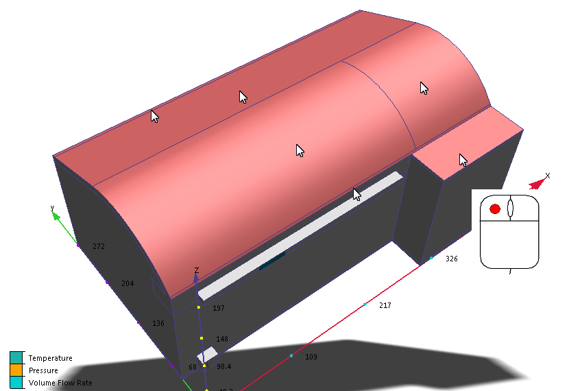
2. Select the six surfaces of the roof.
3. Rotate the model so you can see the surfaces on the left side.
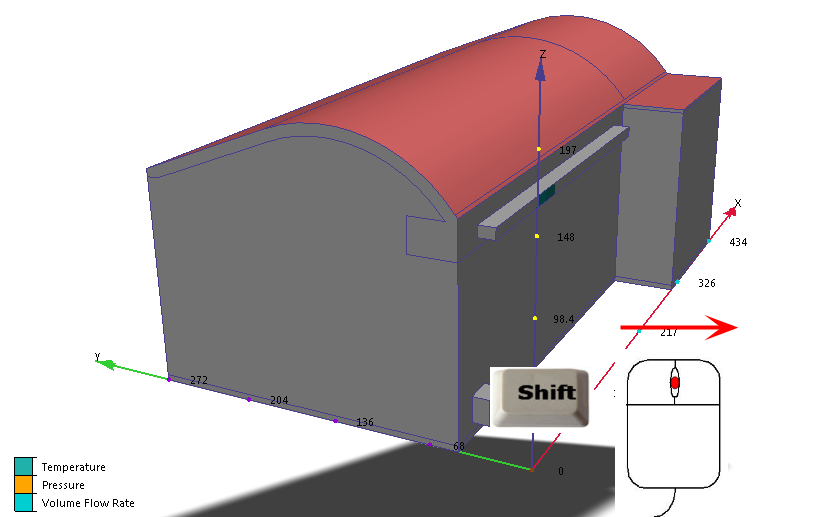
4. Select the two surfaces on this side.
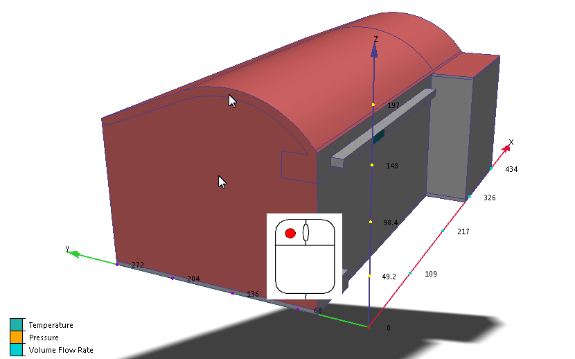
5. Rotate the model so you can see the surfaces on the front side (opposite the supply and return) of the hall.
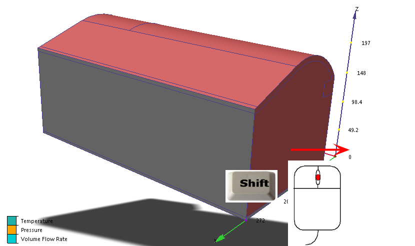
6. Select the two surfaces on this side.
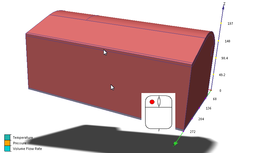
7. Rotate the model so you can see the surfaces on the other small side.
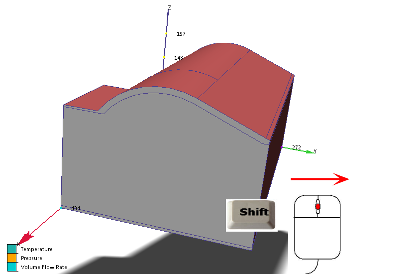
8. Select the final two surfaces.
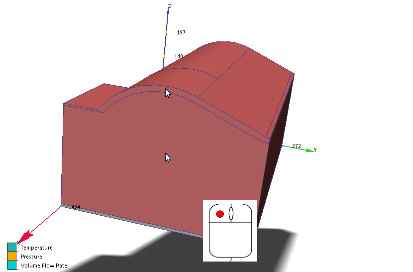
Why didn't we pick the wall with the supply and return? This is an internal wall, and is shared with another room that is at about the same temperature as the exhibit hall. If this had been an external wall, we would have applied the film coefficient to it as well.
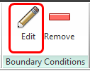
9. Click Edit from the Boundary Conditions context panel:
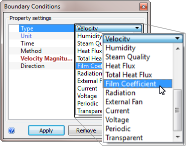
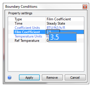
10. On the Type row, select Film Coefficient.
11. On the Unit row, make sure BTU/ft2/h/R is selected.
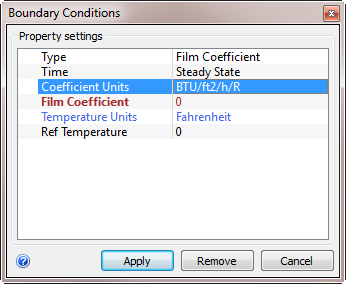
12. On the Film Coefficient row, enter 3.5.
13. On the Ref Temperature row, enter 100.
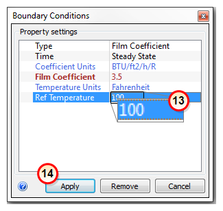
14. Click Apply.
What it should look like...
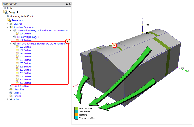
15. To verify that the film coefficient boundary condition is correctly applied to the exterior surfaces, check the Design Study Bar and the colored stripe on the surfaces:
- a. On the Design Study bar, the Film Coefficient condition should be listed with values of 3.5 BTU/ft2/h/R and 100 Fahrenheit.
- b. There should be a colored stripe on the exterior surfaces that corresponds to the legend.
