The Analysis Parameters dialog (
Setup Model Setup Parameters
, or right-click Analysis Type in the tree view and choose Edit Analysis Parameters) is used to set up the calculation of the Riks analysis.
Model Setup Parameters
, or right-click Analysis Type in the tree view and choose Edit Analysis Parameters) is used to set up the calculation of the Riks analysis.
Set up Events
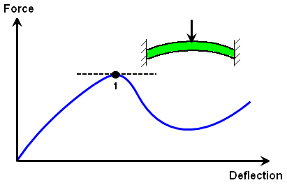
Any static analysis (Riks is a subset of static) must be statically stable to calculate a solution. In a nonlinear analysis, a model that starts out being statically stable can become unstable due to large deflections or material nonlinearities. Snap-through behavior and buckling are two examples of models that may become statically unstable. Riks Analysis is a special method to capture the behavior after the instability. In Figure 1, Riks analysis will continue to calculate the results (follow the force-deflection curve) after point 1. Other static analysis types may fail to find the curve after point 1. (An analysis with the complete Mechanical Event Simulation package can succeed because of the stability due to inertia.)
|
|
| Figure 1: A Snap Through Becomes Statically Unstable Where the Tangent to the Force-Deflection Curve is Horizontal (point 1). |
In a normal MES or nonlinear static stress analysis, the Duration and Capture rate fields on the Load Curves tab of the Analysis Parameters dialog are used to define the length of the analysis, and the applied loads follow a specified time history or load curve. As the time proceeds uniformly, the applied loads are scaled based on the load curve, and the displacements are calculated. The calculated displacements are usually nonlinear with time. The displacement results do not increase uniformly with time.
In a Riks analysis, the Total number of steps field on the Event tab of the Analysis Parameters are used to define the length of the analysis. (Since the analysis is static, time really has no significance. The number of time steps is really what is being set.) As time proceeds uniformly, the displacements are incremented at a uniform rate, and the force required to cause the displacement are calculated. The calculated forces are usually nonlinear with displacement (or time), such as in Figure 1.
The first calculation step multiplies all the applied nodal forces and moments by the value entered in the Initial load factor increment field. (The load curve number that the load is applied to has no meaning.) This load then creates a displacement, and this displacement is incremented at each step of the analysis. (If the analysis were linear, the applied loads would be linearly interpolated between a multiplier of 0 at time 0 to a multiplier of Total number of steps x Initial load factor increment at the end of the analysis.) For any other loads to be considered (pressures, gravity and so on.) you should run a standard MES/nonlinear structural analysis up to the point when the loads reach the appropriate magnitudes. Then you should save the analysis as a new filename and restart the analysis using the Riks method. Prescribed displacements should not be used in a Riks analysis.
If the Magnitude of load factor reaches check is activated, the analysis will stop once the load factor has been incremented above the value in the adjacent field. If the Magnitude of displacement at probe check box is activated, the displacement magnitude of a specific node will be monitored at each time step. Once the magnitude exceeds the value in the adjacent field, the analysis will stop. The node will be specified in the display area by adding a nodal probe: select a node, right-click in the display area, and choose the Add pull-out menu and the Nodal Probe command or use SetupModel SetupProbes. (The probe needs to be added to the model before accessing the Analysis Parameters dialog: see Loads and Constraints: Probes.)
The typical result of a Riks analysis is the load that causes the instability. This can be obtained by comparing the displacements in the Results environment and the load multiplier from the log file. See the page Setting Up and Performing the Analysis: Performing the Analysis: Performing A Nonlinear Analysis for a description of the log file.
Advanced Settings
The advanced analysis options can be accessed by pressing the Advanced button on the Analysis Parameters dialog. For more information, see Advanced Settings.