Mesh MeshEnhance Surface MeshOptionsFeatures/Refinement tab
General Parameters
Pre-Conditioning Factor: The pre-conditioning factor indicates how much larger than the element size you wish the surface mesh enhancer to search to connect close feature line nodes.
The default value is 1.2, indicating that the surface mesh enhancer will increase the mesh size by up to a factor of 1.2 to bridge the space between adjacent feature lines. A larger value (up to maybe 2) typically provides better results if your model has many areas with long, narrow features.
Quad Split Internal Node Angle: The surface quad internal node angle (in degrees) describes the maximum internal angle of any surface quad. If the internal angle of a quad is larger, the surface mesh enhancer divides the quad into two triangles.
Quad Split Fold (Warp) Angle: The quad warp angle (in degrees) describes the maximum out-of-plane angle between any two triangles that you can divide a quad element into. If the warp of a quad is larger, the surface mesh enhancer divides the quad into two triangles. The resultant line that comes from splitting the quad will be layer number 3.
Curve Angle: A feature segment is created along the common edge of two triangles that form an angle larger than the feature angle. These feature segments are connected together to form feature curves. Feature curves are initially divided where they intersect other feature curves or when the cumulative angle along the curve is larger than the curve angle. The resulting feature segments are then further divided based on the mesh size.
The curve angle (in degrees) describes how general curves are broken up. For example, if you have a circle with a size smaller than the mesh size, it may be divided into two lines. By specifying a curve angle, it ensures that the circle is divided at least every n degrees.
You will usually not need to change the curve angle. Its primary purpose is to decrease the mesh size along feature curves with a small radius of curvature.
The surface mesh enhancer tries to mesh feature curves so that the length along the feature curve between mesh points is as close as possible to the mesh size. Without the Curve Angle option, the surface mesh enhancer would mesh small holes (radius less than the mesh size) into too few segments.
The surface mesh enhancer divides feature curves whenever the angle between the starting segment and the current segment is larger than the curve angle. A feature curve is made up of simply connected feature segments. The edge between two triangles is a feature segment if the angle between the planar normals of the triangles is larger than the feature angle.
The curve angle prevents small holes, with circumferences less than the mesh size, from being reduced to a point which cannot be meshed.
The curve angle is used in the following way. The feature line segments are connected together to form feature curves. These feature curves are divided at nodes connected to more than two feature curves to create non-intersecting feature curves. The non-intersecting feature curves are then divided whenever the angle between the current segment and the initial segment of that curve is larger than the curve angle. The non-intersecting feature curves are meshed (broken into lines) based on the length of the curve, the mesh size and any mesh refinement close enough to affect the curve. Values larger than 90 degrees should not be used.
The image below gives a visual explanation of a curve angle. Whenever the angle between the starting segment and the current segment is larger than the curve angle, a new starting segment is created and the starting point of that segment becomes a node in the meshed model. If the points on a feature curve are named A, B, C, D, E, F and the angles between segments are:
AB to BC = 30
BC to CD = 28
CD to DE = 15
DE to EF = 20
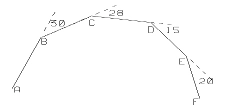
Figure 1
Whenever the angle between the starting segment and the current segment is larger than the curve angle, a new starting segment is created and the starting point of that segment becomes a node in the meshed model. If the curve angle is 31 degrees, then the segments CD and EF will be new start segments and points A, C, E and F will remain nodes in the final model.
If the curve angle is 29 degrees, then segments BC and DE will be new start segments and points A, B, D, and F will remain nodes in the final model. If the curve angle is 31 degrees, then segments CD and EF will be new start segments and points A, C, E, and F will remain nodes in the final model. If the curve angle is 60 degrees, then segment DE will be new start segment and points A, D, and F will become nodes in the final model.
Example
The curve angle affects how segment curves are divided. Figure 2 shows the feature lines obtained from setting the curve angle to 70 degrees. For this case, the four segments at the top of the cylinder are meshed as a pair of elements that are not connected to the rest of the model. See Figure 3.
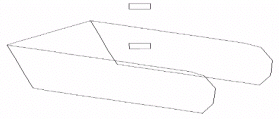
Figure 2: Feature Lines for the Tank Model with a Curve Angle of 70 Degrees
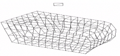
Figure 3: The Tank Mesh with a Curve Angle of 70 Degrees
You can easily avoid this situation by using a smaller curve angle, using a smaller mesh size, or using a smaller feature angle. Figure 4 shows the same model meshed with half the mesh size. For this case, the mesh size is small enough so that the cylinder is divided into more than 4 segments.
Figure 5 shows the model meshed with a feature angle of 10 degrees. Feature curves are divided whenever they intersect other feature curves. Reducing the feature angle creates enough feature curves to resolve the top cylinder. Figure 6 shows the feature lines created with a feature angle of 10 degrees. Once all of the features are resolved with the feature angle, the feature curve does not affect the results.
Figures 5 and 6 are also identical to the results obtained by using a curve angle of 10 degrees. It is often useful to try small curve angles if you have problems getting the surface mesh enhancer to mesh a model. You can reduce the curve angle so that it is small enough to resolve the original feature segments. If the feature segments in the original model are similar in size and not close to a much larger feature line, then the surface mesh enhancer can generate a reasonable mesh. One of the results of choosing a small curve angle is that more elements are generated near curving boundaries.
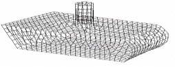
Figure 4: The Tank Model Meshed with Half the Mesh Size
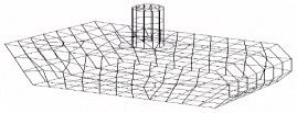
Figure 5: The Tank Mesh with a Feature Angle of 10 Degrees
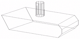
Figure 6: Feature Lines for the Tank Model with a Feature Angle of 10 Degrees
Refinement Controls
Refine Near Short: This option will cause the surface mesh enhancer to refine the mesh along the short feature lines. This is useful if a short feature line is next to a longer feature line. It is especially useful if the model contains a few small holes.
Refine Near Gap: This option will cause the surface mesh enhancer to refine the mesh around small gaps between features. It is useful when the edge of one feature is much closer than the current mesh size to another feature.
Refinement Range: This specifies the transitional distance between the refined mesh size and the specified mesh size. The value in this field is a multiple of the mesh size. A small value will create fewer elements, but it may prevent the surface mesh enhancer from creating a proper transition region.
Once the surface mesh enhancer refines the model for a specific mesh size and refinement, the refinement range can be altered to improve the quality or decrease the number of elements. If the range is decreased, the transition region will be sharper and the number of elements will be reduced but poor quality elements may be produced in the transition region. If the range is increased, you will have a large transition region, a large number of elements, but lower chance of poor quality elements.
Clean Initial Triangles: This command will remove thin feature triangles that sometimes occur in stereolithography files. Feature triangles are triangles with two lines as feature edges. If the triangle height is greater than the input value, then the surface mesh enhancer will try to remove it.
If the specified value is negative, then the absolute value of the specified value times the mesh size is used as the feature clean height.
Clean Feature Lines: If three connected nodes are connected to 3 quads, 4 quads, and 3 quads respectively, the region can be topologically simplified by replacing all 10 quads with 4 quads. This usually makes a cleaner mesh and smoothing helps readjust the quad angles. If the outer boundary of this region is along features, then smoothing will not change any of the angles. For this case, we do not want to create quads with large internal angles. The 3-4-3 to 4 cleaning operation is not performed if a boundary angle between feature nodes is greater than the specified angle.