PVDesigner is a program in Autodesk Simulation that allows you to easily create intersecting cylinders or, more specifically, pressure vessels. This package will take the specifications (dimensions) you give it and will create a meshed model of either plate elements or bricks. Figure 1 shows the interface.
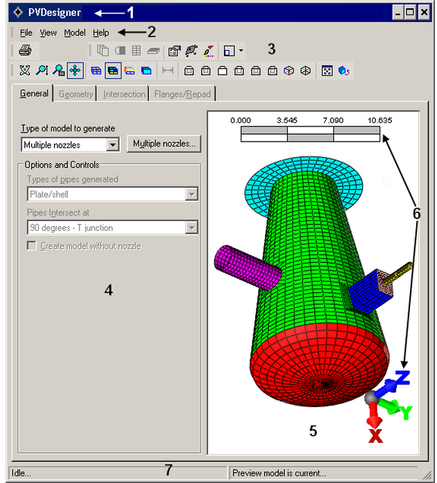
Figure 1: PVDesigner Interface
- Title Bar: The Windows standard title bar displays the program name and the model name.
- Menu Bar: The menu bar is located just below the title bar and contains the pull-down menus.
- Toolbars: The dockable toolbars provide you with quick access to many PVDesigner commands. Use the View
 Toolbars command to choose which toolbars to display.
 - Input Area: The input area is where you enters the dimension of the various segments of the vessel. Some input is also entered in pop-up dialog windows.
- Preview Area: The Preview Area shows the model as it is being built.
- Miniaxis and Scale Ruler: The miniaxis shows your viewpoint with respect to the three dimensional working area and the scale ruler shows the relative size of the model. Use the Model Preferences MiniAxes/Dimension Scale command to control the visibility of these items.
- Status Bar: The status bar displays important messages about the model. For example, attempting to place a 5 foot diameter nozzle on a 3 foot diameter vessel will generate a warning about the sizes. Keep an eye on the status bar.
To access PVDesigner, click  New. Double click the PVDesigner icon. The PVDesigner dialog box will appear after you select a filename, analysis type and unit system.
Once a mesh has been created with PVDesigner, the input parameters (cylinder size, nozzle dimensions, and so on) can be modified by using the Tools EditPressure Vessel command. When finished in PVDesigner, any previously defined input in the user interface (Element Definition, loads, hand-built parts, and so on) will be retained and merged with the new mesh of the vessel.
- Only one vessel per model can be created as PVDesigner puts the same vessel into all design scenarios.
- The input for PVDesigner uses the Model Units. Activating a different Display Units before modifying the vessel with Tools EditPressure Vessel has no effect.
|
Capability |
Single Nozzle Vessel |
Multiple Nozzles Vessel |
|
Model |
||
|
Plate or Shell elements |
Yes (mesh or IGES file) |
Yes (mesh or IGES file) |
|
Solid elements |
Yes (mesh or IGES file) |
Yes (mesh only) |
|
Main Cylinder |
||
|
Create vessel with no nozzle |
Yes |
Yes |
|
Tapered cylinder |
No (use Additional Length on head) |
Yes |
|
Zero length cylinder |
No |
Yes |
|
Partial cylinder in hoop direction |
Yes |
No |
|
Flanges on main cylinder |
Yes |
Yes |
|
Nozzles |
||
|
Nozzle types on cylinder |
Round |
Round, Elliptical, Rectangular |
|
Repad at each nozzle |
Yes |
Yes |
|
Feature region at nozzle |
Yes |
No |
|
Nozzle on heads |
Yes |
Yes |
|
Nozzle types on heads |
Round, Elliptical, Rectangular |
Round, Elliptical, Rectangular |
|
Tapered Nozzle |
On heads only |
Yes, main cylinder and heads |
|
Heads |
||
|
Heads on cylinder |
Yes |
Yes |
|
Heads on nozzle |
Yes |
Yes |
|
Truncated Cone |
Yes (use tapered additional length) |
Yes (use tapered additional length) |
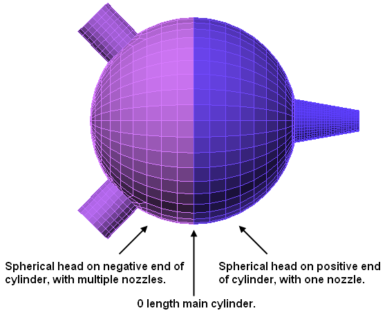
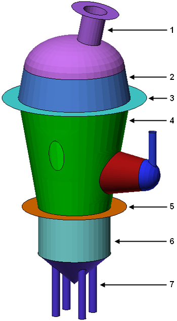
In many cases, complex vessels can be created with a single PVDesigner model by using a combination of the main cylinder, nozzles, heads, and nozzles on the heads. In other cases, multiple models can be created with PVDesigner and merged together in Autodesk Simulation. (Create each model separately, then use Merge.) Examples are shown in Figures 2 and 3.
|
|
| Figure 2: Spherical Vessel with Multiple Nozzles |
|
|
|
|
| Figure 3: Example PVDesigner Vessel with Multiple Nozzles and Heads | |
The steps to create a vessel with a single nozzle are slightly different than the steps to create a vessel with multiple nozzles (such as Figure 1).