Flaws and defects in structures and components sometimes lead to disastrous results even though the stress level in a perfect structure may indicate a satisfactory design. The study of crack initiations and growth is a complicated topic which involves physics, chemistry, mechanics, and so on. The engineering field of fracture mechanics was established to develop a basic understanding of such crack propagation problems. For example, engineers usually want to know the conditions under which an existing crack will continue to grow.
The fracture analysis supports the following features:
- 2D and 3D brick models with elastic and elasto-plastic nonlinear materials. Elements can include midside nodes. Tetrahedron elements are supported for Linear Static and MES analyses.
- Analysis types are supported are the following:
- Static Stress with Linear Material Models
- Mechanical Event Simulation (MES)
- Static Stress with Nonlinear Materials
- MES Riks Analysis.
- Thermal loads.
- Dynamic loads and effects (although some of the calculation procedures are based on quasi-static theory).
- Crack growth direction and stress intensity factors based on mode separation.
Furthermore, the theory of fracture mechanics implemented are based on the following:
- The cracks do not propagate during the analysis.
- The surfaces of the crack do not have any loads applied to them.
Procedure
Fracture analysis is a post-processing function, meaning that the stress analysis is performed first, and the fracture analysis is performed on the existing results in the Results environment (post-processing). The basic steps to performing a fracture analysis are as follows:
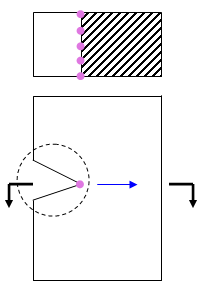
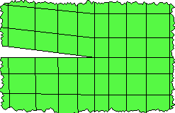
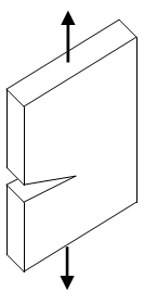
- Create a mesh of the model that includes the crack or defect. A crack is a separation between elements. The tip of the crack should be a sharp point. See Figure 1.
- Perform a stress analysis.
- Define the parameters of the crack or cracks in the Results environment using the tree view.
- Run the fracture analysis from the Results environment.
- Review the results.
|
A part with a crack (exaggerated) |
detail of mesh around crack. |
|
| Key: | |
|
| |
||
| |
||
| Figure 1: Crack Terminology | ||
Define the Crack
The parameters associated with each crack are entered in the Results environment using the Fracture Analysis branch of the tree view. Right-click the branch and choose New to add a crack (or Edit to edit an existing crack definition). These actions open the Fracture Crack Definition dialog. The input is entered on the following tabs: (Refer also to Figure 1.)
Front tab
The Front tab is used to specify the nodes that belong to a crack (the crack front) and the approximate direction in which the crack will grow.
- Use the Selection command to select the nodes at the tip of the crack. If midside nodes are included in the part, those nodes must also be selected. A given node cannot be assigned to more than one crack.
- Click the Add Selected button to add the nodes to the list.
- Using the propagation direction X, Y, and Z columns, enter the virtual crack extension direction (the direction normal to the crack front). This direction affects the results, especially the calculations of KI and KII. In general, the direction normal to the plane of the crack, the tangential direction of the crack front and this virtual extension direction generate an orthogonal frame. See Figure 2.
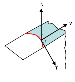
A slice through the plane of the crack. Axis N is perpendicular to the plane of the crack. Axis T is tangent to the crack at each point. (The crack front is shown in red.) Axis V is the virtual crack extension direction and is perpendicular to both N and T.
Figure 2: Virtual Extension Direction
Tip: If the direction of the crack growth is the same for all nodes, enter the X, Y and Z directions for the first row. Then highlight the row, right-click, and choose Copy Direction to Others. If direction is the same for a series of sequential nodes but changes in groups, then add the first node to the list, enter the direction, then add the remaining nodes from the group to the list. The crack direction for newly added nodes is set to the same as the last node in the list. Repeat for the next group of nodes.
- Using the propagation direction X, Y, and Z columns, enter the virtual crack extension direction (the direction normal to the crack front). This direction affects the results, especially the calculations of KI and KII. In general, the direction normal to the plane of the crack, the tangential direction of the crack front and this virtual extension direction generate an orthogonal frame. See Figure 2.
- If the crack front has no beginning and end, then activate the Crack Front is Closed option. For example, a crack around the outside of a cylinder is continuous; therefore this option needs to be activated. A crack across the thickness of a bar begins on one face and ends at the other face; this option does not need to be activated.
Highlighting a row in the Front list will highlight the corresponding node on the model. Use the Remove button as needed to remove the selected rows from the list.
- The order of the nodes in the list needs to be in the same order as the crack front, from one end of the crack to the other. If a node is out of order, highlight the row in the list, right-click, and choose Move Up or Move Down to move the selected row.
- The node list can also be sorted based on the X, Y, or Z coordinates of the nodes (not to be confused with the X, Y, Z crack propagation directions shown in the list). If only one row is highlighted when you right-click, the options Sort By - Coordinate will sort the entire list by the chosen direction. If multiple rows are selected when you right-click, the options Sort By - Coordinate will sort only the selected rows.
Region tab
Fracture analysis only needs to be performed on the elements surrounding the crack tip. It does not need to be performed on the entire part or model. Therefore, use the Region tab to indicate which elements are used in the analysis. There are two ways to indicate which elements to use:
- Rings of Elements When chosen, use this field to enter how many rings of elements around the crack tip should be selected. When you type a number and press Enter (or click in the Region list), the elements that make up the ring will replace the current entries in the list. See Figure 2. Generally, 3 or 4 rings of elements are sufficient depending on the mesh size. (The goal is to choose the elements around the crack tip with a stress higher than the nominal stress value.)
- Specified When chosen, selected elements are added to the list. Use the Selection command to select the elements around the crack. Then click the Add Selected button to add the elements to the list.
Highlighting a row in the Region list will highlight the corresponding element on the model. Use the Remove button as needed to remove the selected rows from the list.
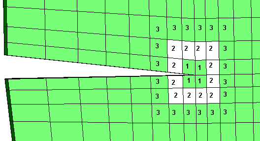
The numbers correspond to the elements that would be selected when 1, 2, or 3 rings of elements are designated. (Two rings would include all elements shown with '1' and '2'; three rings would include all elements shown with '1', '2', and '3', and so on.)
Figure 2: Examples of Rings of Elements
Output tab
The Output tab controls what calculations are performed.
The choices in the Propagation Direction Criterion control which theory is used to calculate the direction of the crack growth. These criteria predict slightly different angles for the initial crack propagation, but they all have the implication that KII = 0 at the crack tip as the crack extends. The options are as follows:
- Maximum Tangential Stress This criterion is also called as the Maximum Hoop Stress criterion. The direction of crack growth is obtained under the assumption that the crack will propagate in the direction with at the crack tip. In fracture analysis simulation, especially numerical computation, the direction is calculated by:

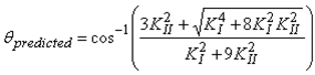 where ϑ
predicted
< 0 if KII > 0 or ϑ
predicted
> 0 if KII < 0, and KI and KII are the stress intensity factors for Mode I and Mode II respectively. The propagation angle ϑ
predicted
is with respect to the crack plane.
where ϑ
predicted
< 0 if KII > 0 or ϑ
predicted
> 0 if KII < 0, and KI and KII are the stress intensity factors for Mode I and Mode II respectively. The propagation angle ϑ
predicted
is with respect to the crack plane. - Maximum Energy Release Hayashi and Nemat-Nasser (1981) provided a series of direction-dependent coefficients c
ij
. At the crack tip, the stress intensity factors for different direction can be expressed as Also,
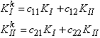 The maximum energy release rate criterion postulates that the crack grows in the direction that maximizes G k .
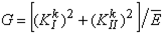
- KII = 0: This criterion postulates that a crack will propagate in the direction that makes in the equations
 Note: The crack propagation calculations are only applicable to elastic models in a quasi-static loading. Results are created for other situations (plasticity and dynamic analyses), but the results will deviate from reality depending on the amount of nonlinear and dynamic effects.
The fracture analysis can be performed on the chosen load cases or time steps instead of the entire analysis. Enter the first and last load case/time step to be analyzed with the Start and End fields. Generally, only the load cases/time steps around the highest stresses need to be analyzed.
 Options Results tab and activate the option Display warning message when fracture analysis results become invalid due to changes to crack definitions.
 Perform Fracture Analyses
To analyze all the defined cracks, right-click the Fracture Analysis branch of the tree view and choose Analyze All. To analyze individual cracks, select the cracks in the tree view, right-click, and choose Analyze. Analyzing selected cracks does not delete the results for other cracks. The fracture analysis on an MES model may be noticeably slower than on a static model since the fracture analysis computes the velocity and accelerations for each step.
The results for each crack are written to a separate file, and then all the crack results are combined together. The Results environment reads the results from the combined file. If a crack is deleted or modified (right-click the entry in the tree view, then Delete or Edit), the results for the other cracks need to be recombined. These actions could produce a noticeable delay.
View Results
After the fracture analysis is completed, the Results Contours Other Results panel will contain the following items:
- Fracture: J Integral: Display the J Integral results (the strain energy release rate of nonlinear elastic materials). The theory of J-Integral implies that the calculation is suitable only for monotonic loading of elastic-plastic materials.
- Fracture: Stress Intensity Factor KI, KII, and KIII: Display the stress intensity factors for the three deformation modes (see Figure 3). Comparison of the stress intensity factor to the appropriate critical stress intensity factor (or fracture toughness) will determine whether the crack will propagate or not. Note: The stress intensity factor results are only applicable to elastic models in a quasi-static loading. Results are created for other situations (plasticity and dynamic analyses), but the results will deviate from reality depending on the amount of nonlinear and dynamic effects.
- Fracture: Crack Growth Direction: Displays the calculated direction of the crack growth as a unit length vector.
|
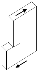
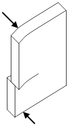
(a) Mode I: tension. |
(b) Mode II: in-plane shear |
(c) Mode III: out-of-plane shear |
|
Figure 3: Deformation Modes |
||
All the results are displayed as vector arrows at the nodes defined along the crack front. The magnitude and color of the arrows represent the magnitude of the selected result. The direction of the arrow represents the direction of the crack growth.
Select Nodes) and inquire on the results (Results Inquire Inquire Current Results) to get the crack propagation direction and the magnitude of the result. The components of the results are the direction components of the crack propagation, multiplied by the result. Thus, the direction of the arrows will change by 180 degrees when the displayed result is negative. The result itself is not a vector and does not have components. Common Fracture Analysis Error Messages
The crack tip node must be listed in order from one end to another. The mid-side node must be included for second-order elements. No nodes along the crack front can be skipped!
- The nodes for the specified crack were not entered in sequential order along the length of the crack. If used, include the midside nodes in the list. Edit the crack and review the list of nodes on the Front tab. Highlight each row of the list to see which node is selected on the model. (The nodes are easier to see on the model if you display the model without shading: View Appearance Visual Style Features or View Appearance Visual Style Mesh.) The first row should highlight a node at one end of the crack, the second row should highlight the next node, and so on. When a node is found to be out of order, right-click the highlighted row and choose Move Up or Move Down to move the position of the node within the list.
The Element Type n is not supported for Fracture Analysis
- The elements selected around the crack tip include types that are not supported (such as shells). Only 2D and brick elements are supported. Linear Static and MES analyses also support tetrahedron elements.