For linear structural analyses, pressures or tractions can be applied to surfaces of 2D, plate, membrane, thin composite, thick composite, brick, and tetrahedral elements. For nonlinear structural analyses, pressures or tractions can be applied to surfaces of pipe, 2D, 2D kinematic, 2D hydrodynamic, shell, membrane, brick, tetrahedral, 3D kinematic and 3D hydrodynamic elements.
What does a pressure/traction load do?
- Applies an even distribution load (force per unit area) over the selected area.
- A pressure can be applied to the linear and nonlinear structural elements that are listed at the top of this page. The pressure will be applied normal to the faces of brick, tetrahedral, plate, thin composite, thick composite, shell, membrane, 3D kinematic, and 3D hydrodynamic elements. It will be applied normal to the edges of 2D, 2D kinematic, and 2D hydrodynamic elements. It will be applied as internal pressure to pipe elements.
- For linear analyses, a traction can be applied to plate, brick, and tetrahedral elements. A traction applies a pressure that is oriented in a specific direction.
- For nonlinear analyses, a traction can be applied to all of the nonlinear structural elements that support pressures, except for pipe elements. The traction will be a pressure oriented in a specific direction.
Apply Pressures/Tractions
If you have surfaces selected, you can right-click in the display area and select the Add pull-out menu and then choose the Surface Pressure/Traction command. You can also access this command via the ribbon (Setup  Loads Pressure). You can click the ribbon command either before or after selecting the model surfaces where you want the load applied.
If you are performing a nonlinear analysis or a transient stress (direct integration) analysis, select the load curve that the pressure or traction will follow in the Load Curve field. Press the Curve button to define a load curve in the Load Curve Editor, or use the Setup Model Setup Parameters dialog box.
For nonlinear analyses only:
- Specify a value other than 1 in the Multiplier field to have an additional multiplier applied to this load.
- For the load to maintain the same relative orientation (with respect to the model) as it deforms, activate the Follows Displacement check box.
Pressures
To apply a normal pressure, select the Pressure button (this is the default). Specify the magnitude of the pressure in the Magnitude field.
For 2D, and solid elements, a positive pressure is directed into the element and a negative pressure is directed away from the element.
For plate, thin composite, thick composite, and shell elements, a positive pressure points away from the element normal point and towards the elements. A negative pressure points towards the element normal point and away from the elements. The element normal point is defined in the Orientation tab of the Element Definition dialog box.
Tractions
To apply a traction load to any of the supported elements, select the Traction button (it will be grayed-out for non-supported elements). Specify the component of the traction in each of the global directions in the X Magnitude, Y Magnitude, and Z Magnitude fields.
Notes on General Shell Elements:
Nonlinear General Shell elements take the thickness of the element into account for pressure loading.
(The other planar elements that support hydrostatic pressure loads – plate, membrane, co-rotational shell, and thin shell – consider the pressure to be applied at the midplane. The type of shell element is set using the Element Formulation selector within the Advanced tab of the Element Definition dialog box.)
General shell elements have options to apply the pressure or traction load to the Top side, Bottom side, Both Sides, or Neither side. The bottom side of the element is the side facing the element normal point, as defined in the Element Definition dialog. A positive pressure points into the element regardless of the side to which it is applied.
Although the areas of the top and bottom sides of the element are equal in the stress-free condition, large displacement effects can stretch the two surfaces differently. Thus, although uniform pressures of -1000 on the top and 1000 on the bottom may appear to be identical graphically, the results can be different. A similar situation occurs with hydrostatic pressure loads. In addition, for inclined or curved surfaces, taking the thickness into consideration changes the effective fluid depth where the fluid contacts the elements, and therefore affects the hydrostatic pressure (depending upon whether the load is applied to the top or bottom face of the elements). See the figures below.
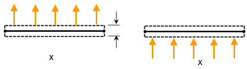
(a) Planar element, one with a negative pressure applied to the top side of the element (left side of figure) and one with a positive pressure applied to the bottom side of the element (right side of figure). In the stress-free condition, the area of the top side and bottom sides are the same. (The element normal point is indicated by the X.)
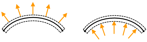
(b) As the elements stretch, the area of the top and bottom sides also stretch. Thus, the total force due the same pressure on the top as on the bottom may be different. In this example, the top side stretches more than the bottom side, so the force in the model with the pressure on the top is higher than the force in the model with the pressure on the bottom.