The 3D Drucker-Prager material model is used to model geological materials, such as soils, clays and rocks. This material model uses a yield function defined by
|
|
where:
|
|
|
|
|
|
 (3)
(3)
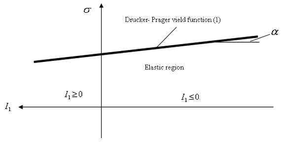
Figure 1: Graph of the Drucker-Prager Yield Function
The Drucker-Prager yield criterion will be identical to the von Mises perfect plastic yield criterion if the following criteria are met:
|
|
 (5)
(5) Inputting the Parameters
The parameters α and β are defined in the Type of Data tab of the Element Material Specification dialog. If the Model constants option is selected in the Type of data input drop-down box, the parameters α and β will be defined in the Alpha and Beta fields, respectively. If the Soil mechanics coefficients options is selected in the Type of data input drop-down box, the parameters α and β will be calculated from common parameters used to refer to geologic materials. a and ß will be calculated from the values entered in the Cohesion and Angle of Friction fields from the following equations:
|
|
|
|
where ϑ represents the value in the Angle of Friction field and c represents the value in the Cohesion field.
Modified Drucker-Prager Yield Criterion/Yield Function
The Drucker-Prager yield criterion does not take into account two properties of geological materials. First, most geological materials provide little or no resistance to tensile loads. Second, the yield surfaces and strengths of geological materials often depend on the pressure loads. The Modified Drucker-Prager material model will account for these properties. This model includes three sections as shown in Figure 2. The area where I1 is larger than the tension cut-off, Tcut, is defined as the tension cut-off region. The region where I1 is less than the cap yielding function defined as the cap hardening area.
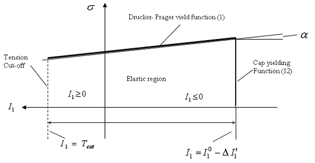
Figure 2: Graph of the Modified Drucker-Prager Yield Function
Tension Cut-off Region
Once the tensile stress exceeds the value T cut , there are three options that can be used to handle the stresses while maintaining the stability of the iterative solution process.
1. A residual stiffness, K res , will be used. This will be calculated as:
|
|
where r res is the residual stiffness factor and K e is the original elastic stiffness. The factor r res must be between 0.0 and 1.0.
2. The three normal stresses will be set to one-third of Tcut and the three shear stresses will be set to 0.
3. All normal and shear stresses will be set to 0.
Cap Hardening Region
The cap yielding function is defined as
|
|
where![]() is the initial cap position, and
is the initial cap position, and![]() is the increment of the cap position due to pressure hardening,
is the increment of the cap position due to pressure hardening,
|
|
 (10)
(10) C1 and C2 are the two cap hardening parameters. Both of these parameters must be less than 0.![]() is the user input coefficient used to define the initial cap position. This coefficient must be less than or equal to 0.
is the user input coefficient used to define the initial cap position. This coefficient must be less than or equal to 0.![]() is the plastic volume strain.
is the plastic volume strain.
The physical meaning of the various cap function coefficients is shown in Fig. 3. From this figure, it may be seen that the coefficient C1 represents the maximum plastic volumetric strain the material could ever reach, and C2 gives a measurement of the cap position increasing rate.
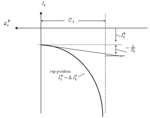
Figure 3: Graph of the Cap Hardening Curve
Input Parameters
Tension Cut-off Region
To include the tension cut-off region, you must select the Included option in the Tension cutoff drop-down box in the Tension Cutoff tab of the Element Material Specification dialog. The value Tcut will be defined in the Tension cutoff coefficient field. To use the first method of handling the stresses past T cut , enter the r res value in the Residual stiffness factor field and select the Based on elastic stiffness option in the Stress after tension cutoff drop-down box. To use the second method, select the Normal stresses set to mean option in the Stress after tension cutoff drop-down box. To use the third method, select the All stresses set to zero option in the Stress after tension cutoff drop-down box.
Cap Hardening Region
To include the tension cut-off region, you must select the Included option in the Cap hardening drop-down box in the Cap Hardening tab of the Element Material Specification dialog. Enter the C1 value in the First cap hardening constant field. Enter the C2 value in the Second cap hardening constant field. Enter the![]() value in the Initial cap position field.
value in the Initial cap position field.