If the Stiffness matrix and force vector check box in the Output tab of the Analysis Parameters dialog box is activated, the stiffness and mass matrices is output to a filename.mtx text file. This document describes how to interpret the stiffness matrix for those who want to use it for other purposes. The file format varies depending on the solver used.
Subspace Solver
The first line of the matrix output file (see Figure 1) contains the following values:
1. The entire stiffness matrix may be too large to solve as one large block of numbers. Thus, the matrix may be split into smaller blocks. The number of rows of the stiffness matrix that appears in a block is given by the equations per block.
2. The number of columns in the stiffness matrix is given by the bandwidth. Each row of the stiffness matrix may be printed on multiple lines of the .MTX file, with up to five (5) numbers per line.
3. Blocks is the number of blocks in the solution, and the number of blocks that the stiffness matrix is split into. For modal analysis, the minimum number of blocks is always two (2).
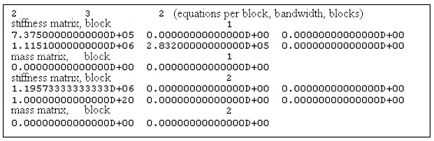
Figure 1: Sample Stiffness Matrix (.MTX)
To understand the entries in the stiffness matrix, refer to figure 2. The stiffness matrix is square and symmetric. The first number on each row of the matrix (keeping in mind that each row may require several lines of output) is the stiffness term on the diagonal. Terms after this are for the upper half of the stiffness matrix. However, each row in the output includes bandwidth number of terms. Thus, one zero (0) is added to each succeeding row of the output.
How do the terms in the stiffness matrix correlate to the model and the nodes? This can be understood from figure 3. The DOF, which stands for degree of freedom, is related to a particular node and motion: either a translation or a rotation. This correlation can be determined by printing the equation numbers with the Global: Output: Equation numbers data option. Figure 4 shows a sample printout of the equations numbers, which appears in the summary file (.ML). In some cases, it may be easier to avoid the bandwidth minimization (Global: Options: Avoid bandwidth minimization).
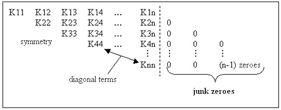
Figure 2: Stiffness Matrix
Shift all the values to the left and you have a square matrix of n by n. This corresponds to the output in the .MTX file.
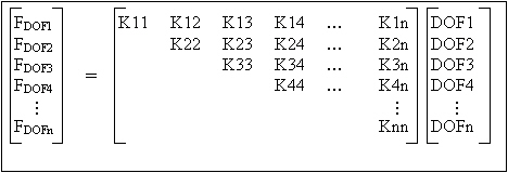
Figure 3: System of Equations
DOFi is a direction (X, Y, or Z) and component (translation or rotation) which can be determined from the equation numbers.
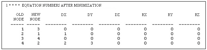
Figure 4: Equation Numbers from Summary File (.ML)
Sparse Solver
There are two sections of the filename.mtx file created by the sparse solver. The first section contains the values on the diagonal of the matrix for both the stiffness matrix and mass matrix. There are four columns as shown in Figure 1 below.
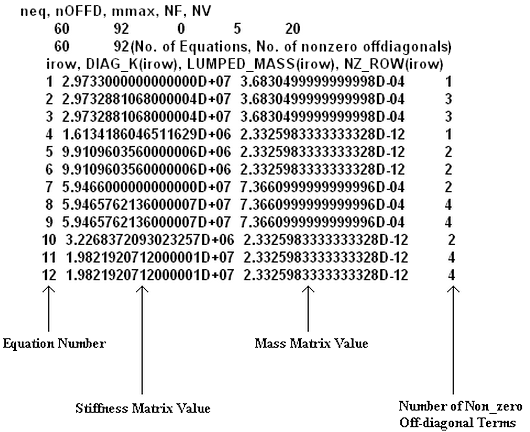
Figure 1: Portion of the First Section of a .mtx File
Therefore the first section defines the diagonal of both the stiffness and mass matrices. Since the mass matrix has no non-zero values away from the diagonal, the mass matrix is completely defined. The second section consists of 3 columns as shown in Figure 2.
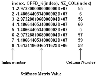
Figure 2: Portion of the Second Section of a .mtx File
Both the first and second sections must be used to build the rest of the stiffness matrix. The fourth column of the first section defines how many non-zero values are in that row. Referring to Figure 1, the first row only has 1 non-zero off-diagonal value and the second row has 3 non-zero off-diagonal values. Therefore in Figure 2, the value for index 1 is located in the first row and the values in indices 2, 3 and 4 are in the second row. This method can be extended to determine the row for each term. Only the non-zero terms are listed in the second column. The value in the third column defines in which column of the matrix the term is located. Referring to Figure 2, the first value is located in column 55. Therefore the values in the first row of columns 2-54 are all 0. Likewise all the values in row 2 in columns 56-60 are 0. (The value in column 1 is on the diagonal and therefore is defined in the first section.) In the second row, there is 0s in columns 3-5, 7-55 and 57-59.The stiffness matrix is symmetric, therefore only the values to the upper right of the diagonal is defined. You can use symmetry to define the lower left half.