The Advanced Controls and Parameters for Contact Pair dialog is accessed by clicking the Advanced button on the Controls and Parameters for Contact Pair dialog. From the Advanced dialog, individual parameters for the contact pair can be specified.
General tab
Contact Stiffness
By default, Automatic is used in the Contact stiffness drop-down box. Contact stiffness for surface-to-surface contact is calculated with the following equation:

where
- f s is the scaling parameter and the default value is 0.1.
- E is the smaller of the Young's modulus for the two materials in the contact pair.
- A is the multiplication of the contact line and the thickness (2D) or contact surface area (3D).
- V is the multiplication of the area of the element and the thickness (2D) or volume of the element (3D).
The ratio, A2/V, is calculated for elements of both the target and contact surfaces. The ratio values are averaged for surface-to-surface contact types. For other contact types, the ratio value for the target surfaces is used. A value of 1.0 is used for this ratio for contacts that involve beam or truss elements.
To use a specific value for the contact stiffness, select the User-specified option from the Contact stiffness drop-down box and enter the appropriate value in the Contact stiffness field. If a value is entered in the Additional contact stiffness field, this stiffness will be added to the Contact stiffness value if one surface penetrates another surface. See Figure 1.
|
|
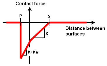
| Figure 1: Contact Stiffness and Contact Distance |
|
Two surfaces come into contact when the distance between the surfaces is less than the Contact Distance (S). Closer than this distance, the contact force at each element is proportional to the amount of compression (S – distance) and the Contact Stiffness (K). When the distance decreases to 0, the parts begin to pass through each other (penetration). The contact force is then proportional to the contact stiffness plus the Additional contact stiffness (Ka) and the amount of penetration. When the distance between the surfaces reaches the Maximum Penetration Distance (P), the contact force goes to zero. |
The value for the contact stiffness should typically range from 1 to 10% (for "Unit" mesh size) of the Young's modulus value for the softer of the two materials in contact. For a mesh size that is too large or too small, you might need small increases or reductions in the percentage, respectively. If the assumed stiffness is too low, excessive contact penetration will occur. If the stiffness is too high, contact oscillation and instability is likely.
Another way to estimate the contact stiffness is to view the contact elements as a group of springs between the nodes of the two surfaces. If the contact force is known - even approximately - then the contact stiffness can be calculated from K=(F/n)/Δ, where F is the contact force, n is the number of nodes in contact, and Δ is the amount of compression in the contact elements to resist the force F/n. Keep in mind that the contact elements need to compress some amount to generate a force, so choosing a Δ of 10% of the contact distance (S) is a good starting point. However, this method could prove practical only for simple contact models with regular geometry.
If you select the Use adaptive contact stiffness method after first step check box, the contact stiffness is automatically adjusted throughout the analysis to provide improved accuracy and convergence. The contact stiffness is adjusts based on the status of the contact (penetration, no penetration). This method can provide more accurate and efficient solutions for some cases. For models that involve contact between parts moving quickly relative to each other or parts that have nonlinear material models, deactivating this check box could prove necessary.
If the stiffness is too small, large penetration of nodes into the master surface is inevitable. If the stiffness is too large, the geometric boundary condition over the contact area is exactly fulfilled, but quite often the equilibrium iteration becomes unstable. High values of contact stiffness will lead to ill-conditioning of the global stiffness matrix and result in poor convergence.
When Contact Occurs (Contact Distance)
By default, the processor will calculate a contact distance from the geometry of the model. The contact distance is the distance between the surfaces at which contact will occur. (See Figure 1.) If two surfaces are closer than this distance, the Contact stiffness will be applied. For a specific value to be used for the contact distance, select the User-specified option from the Contact distance drop-down box and enter the appropriate value in the Contact distance field. To avoid penetration, it is best to set the contact distance to a reasonably large value.
If the contact distance is larger than the initial gap between the surfaces, then an interference is created (Surface to Surface and Point to Surface contact only), and a contact force occurs at the beginning of the analysis which tries to separate the bodies. In this situation, it is typical to see the time step be reduced at the beginning of the analysis until the parts come into their new equilibrium.
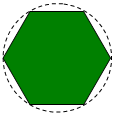
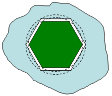
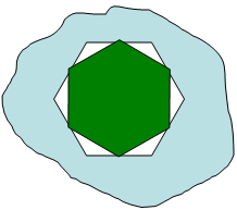
Special considerations are needed for closely spaced, moving parts - such as a shaft or pin inside a hole. Mathematically, the gap between the parts may be smaller than the physical gap. The mathematical gap is determined by the size of the mesh and the approximation of the surfaces. The physical gap is based on the dimensions of the parts. As the approximated surfaces move or rotate, it is possible to create an interference which would not exist in reality. See Figure 2.
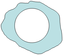
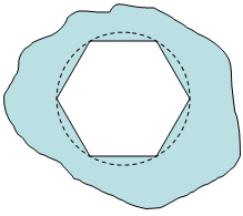
Figure 2: Clearances and Interferences Change When a Part is Meshed
|
1. A hole in a part |
becomes a polygon when meshed. |
|
2. A round pin |
becomes a polygon when meshed. |
|
3. Combined, the two parts may fit without interference in some positions |
but interfere in other positions (even if the physical parts have a clearance). This is due to the approximation of the surfaces. |
To provide the same clearance (or interference) between two meshed parts as the physical parts, the dimensions of the parts and the contact distance may need to be adjusted to get the proper behavior. These are related to the mesh size as shown in Figure 3.
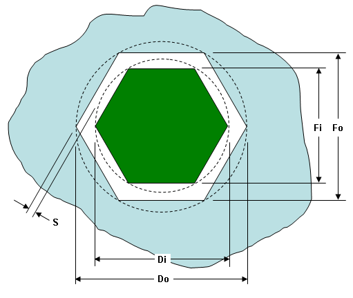
Figure 3: Relationship of a Pin Inside a Hole to Avoid Interference
From basic geometry, one can relate the diameter D to the dimension across the flat F as:
![]()
To avoid an interference fit, the dimensions must be set based on this relationship:
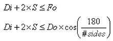
where:
- D, Di, and Do are the physical dimensions (real or theoretical dimensions)
- F, Fi, and Fo are the dimensions across the flats (due to the approximation by the mesh)
- # sides is the number of sides or elements around the perimeter. If the mesh around the perimeter is uniform, then this value is obvious. If the mesh is nonuniform, such as when using mesh refinement points, then the # sides is a hypothetical value based on how many sides (or elements) would exist if the coarsest mesh were used around the entire perimeter. Alternatively, you can measure the largest dimension Fo in the mesh.
- S is the mathematical clearance between the corners of the pin and the flats of the hole. If the surface to surface contact distance is set equal to this dimension, then there will be a 0 clearance gap at some positions of the pin and hole.
For example, take a 2-inch diameter pin inside a 2.010-inch diameter hole, and mesh each with 40 elements. The mathematical clearance S = 0.0019-inch; much less than the theoretical 0.005-inch clearance on each side. To have the 0.005-inch clearance with a contact distance of 0.002-inch, S = 0.007-inch and the inner diameter would need to be 1.9898-inch diameter.
Geometry tab
When to Check For Contact
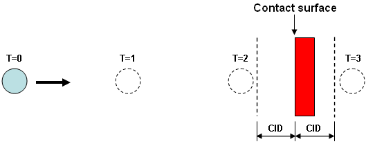
The Contact interaction distance is used to speed the calculations. Contact is only considered if the two surfaces are closer than this value. Thus, if the processor knows the two parts are far apart, there is no need to go through the steps of checking whether they are in contact. You need to be careful that the parts do not move too far from one step to another so that the parts are not in contact at either calculation step, even though the parts actually pass through each other. In this condition, no contact is detected. See figure 4. A value of 0 (which works in some cases but possibly not high speed applications) indicates that the contact distance is equal to the maximum dimension of a surface element on the parts.
|
|
|
Figure 4: Contact Interaction Distance A rapidly moving sphere is shown at four time steps (T=0,1,2,3). Contact is checked only when the bodies are within the contact interaction distance (dimension CID) of each other. In this example, the sphere is outside the contact interaction distance on all time steps, so the fact that it passed through the block is not detected. |
When Parts Penetrate Each Other:
Surface contact is not enforced when a point on the secondary part surface is more than the Maximum penetration distance beneath the primary part surface for this contact pair. (The contact force goes to zero. See Figure 1.) This entry is used to prevent enforcing the fictitious contact between points on the secondary surface which are beneath the primary surface. If this entry has a value of 0.0, then the processor uses the maximum dimension of a surface element as its local maximum penetration distance. We suggest that the user should rarely use any other value beside 0.0 for this entry.
Limiting the Number of Contact Elements
If the parts move significantly relative to each other, the automatic contact updating (on the Surface to Surface Contact main dialog) is the best option to let the processor determine which points are actually in contact on each time-step. But in cases where the parts have little motion relative to each other, a faster analysis can be obtained if the user can minimize the number of contact elements that get generated. Contact is not created between elements which are initially farther apart than the Maximum initial distance. Therefore, contact will never occur between the elements, regardless of how close they move together. This will limit the number of contacts that are checked and thus speed up the analysis.
Imagine a pin inside a yoke and clevis. If the pin does not rotate relative to the yoke, then the left side of the pin will not make contact with the right side of the hole. Thus, setting the maximum initial distance to a small distance -- such as the size of one element -- will create just enough contact elements to connect the pin to the hole at adjacent nodes. The result will be a smaller model and less checking of the contact element status, so the analysis will run faster.
Enlarging Contact Surface
Surface to surface contact can be thought of as an extension of the element's surface, normal to the face of the element. When the surface is convex, this leaves gaps between two adjacent elements where the contacting body can get stuck. The target node can move without being in contact. This causes chatter as it then alternates between contacting the adjacent elements. See Figure 5a. If the Automatic option is selected in the Extend contact element sides drop-down box, the contact element boundaries will be extended by a small amount to account for such gaps. See figure 5b. If the Automatic option is selected, the processor will be able to detect when this is necessary and will extend the length as necessary. If you do not want the length to be extended, select the Avoid option.
|
Target contact node
Two contact areas (highly exaggerated)
|
Two contact areas extended. |
|
(a) Without extending the contact elements, the contact from one element to the next is not smooth as the target node slides across the surface. |
(b) Extending the contact elements gives a smoother contact area as the target node slides from one contact element to the next. |
|
Figure 5: Extend Contact Sides |
|
Smoothing the Contact Surface
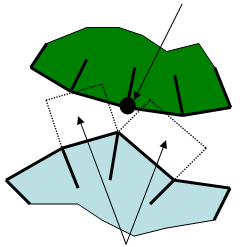
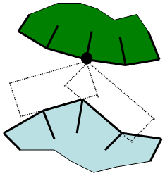
Two issues originate from the non-smoothness of the contact surface, where smoothness is an indication of how much the normal direction changes between two adjacent elements. The first issue is poor convergence and the second is poor results. If two adjacent elements are not co-planar, such as on a curved surface, the normal vector of the contact force experiences a sudden change in direction when a target node travels across the element boundary. Such situations are inevitable as long as discrete geometry is being considered. This non-smoothness can cause oscillation across the element boundary and the target node can become stuck in the element boundary.
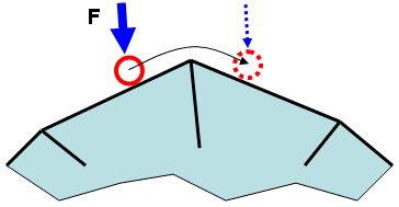
To minimize this situation, set the Extend contact element sides drop-down box to Smoothed by. Selecting this option activates the input field Smoothing factor (0-0.5). Think of the smoothing factor as placing a fillet at the corner of two elements (or two sides of the same element). See Figure 6 for clarification. The smoothing factor is a value between 0 (no smoothing) and 0.5 (the transition region extends to half of the element's edge).
Note that smoothing does not occur at the junction between two different contact surfaces. It only occurs within the confines of each contact surface.
|
(a) A target node (red circle) on another body (not shown) is being forced into contact by the force F while moving from left to right. As the node moves from one element to the next, the direction of the reaction force changes instantaneously, which can lead to convergence difficulty. |
|
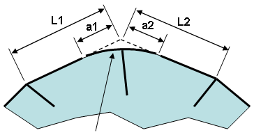
smooth transition (b) By activating the Smooth by option, the sharp corner is eliminated. Thus, the direction of the reaction force changes smoothly as the node (removed for clarity) moves from left to right. The distances a1 and a2 are calculated as follows: a1=smoothing factor * L1 a2=smoothing factor * L2 |
| Figure 6: Smoothing the Contact Surface |
Keep in mind that surface-to-surface contact is always checking whether the nodes on one surface are passing through the surface of another surface. Thus, node on surface A will contact the smoothed surface B, and the node surface B will contact the smoothed surface A, but technically the smoothed surface A does not contact the smoothed surface B.
Contact Element Updating Parameters
Specify the radius for which contact elements will be created each time they are generated in the Search radius field. This field will only be available if the User-defined option is selected in the Updating drop-down box in the Contact Element Updating Parameters section of the Surface-to-Surface Contact dialog.
Timestep tab
If the Invoke automatic time-step reduction method check box is activated, the time step will be reduced automatically once the two surfaces are closer than the distance specified in the Target distance for time-step reduction field. The advantage of this reduction is to anticipate that a smaller time step will be required when contact occurs and to reduce the contact before it occurs. (Note that the Target distance for time-step reduction is compared to the separation of the actual surfaces without taking the contact distance into account.) The time step will be reduced at least to the value specified in the Minimum time-step size for contact field (and usually to a smaller value since the time-steps are reduced by dividing the current time-step by an integer amount). If the Minimum time-step size for contact is zero, then the minimum time-step behaves as if the user had entered the value current time-step/10.
If the Invoke automatic time-step reduction method check box is not activated, the time-step will be reduced only if necessary to satisfy the equilibrium and contact convergence.