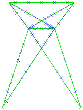
To have the results calculated at more data points, we will divide each of the existing lines into 10 elements. Stresses and displacements are only calculated at the beam element endpoints.
- With the
 Selection
  Select Lines commands active, press Ctrl-A, to select every line within the model.
 - Click
 Draw Modify Divide. Note that you can also access the Divide command from a context menu by right-clicking in the display area.
 - Type 10 in the Number of Lines: field.
- Click OK. The model appears as shown below. Note how the display of endpoints provides visual confirmation that the original beam elements have all been divided.
- Deactivate the
 View Visibility Endpoint Vertices option. Note that without the visible end points, you cannot tell how many segments comprise a beam span. The model appears as shown below.
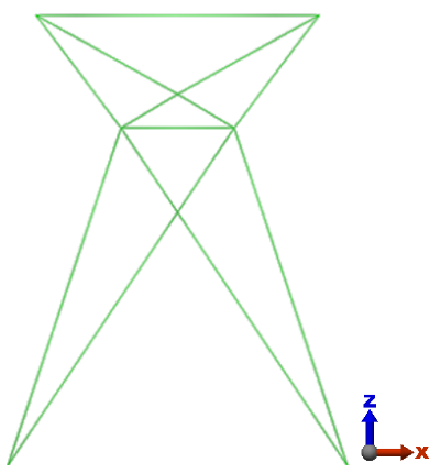
This tutorial is now complete. The model can be used to complete the Beam Tower Static Stress Analysis tutorial.