- Click
 Analysis
  Analysis Run Simulation.
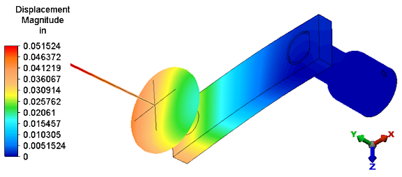
 After solid meshing, the analysis proceeds and the model displays in the Results environment. The displacement magnitude is presented initially by default. The maximum displacement is approximately 0.052 inch.
Note: 3D visualization of beam elements is enabled by default. The beam elements in this model were defined with an arbitrary radius of 1 inch (2 inch diameter) to ensure that they provide a fairly rigid connection to the knob. This size is large relative to the assembly, and disabling 3D visualization will prevent the beams from obscuring the view of other parts. - Right-click the Part 4 heading in the browser (tree view) and deactivate 3-D Visualization.
- Click in a blank portion of the display area to clear the selection of beam elements. The model appears as shown below.
- Click in a blank portion of the display area to clear the selection of beam elements. The model appears as shown below.