When a CAD solid model is imported or opened, the Surface Splitting dialog can appear. Surface splitting is a process of recognizing where two parts have surfaces in contact, and then splitting the surfaces if necessary to get identical surfaces. The benefits of choosing to split the surfaces are as follows:
- The matching of the meshes on adjacent surfaces is better if the surfaces are identical. However,
- The Mesh
 Mesh3D Mesh Settings OptionsModelUse virtual imprinting will create a quality matched mesh without using surface splitting. See the page Meshing Overview: Meshing CAD Solid Models: Model Mesh Settings: Model for details.
 - For analysis types that support smart bonding, it is not strictly necessary to have a matched mesh. See the page Meshing Overview: Creating Contact Pairs: Types of Contact for the analysis types that support smart bonding.
- The Mesh
- Some loads should only be applied to free or exposed surfaces, such as pressure and convection. If a large surface is not split where it is covered by other parts, then the load will be applied to a larger area than intended. See the figures below.
- Surface splitting must be used if the Fluid Generation is going to be used (create a new part from the solid parts to use in a fluid analysis).
The potential disadvantages of surface splitting are the extra time required when opening the model, and the possibility of generating surfaces which are harder to mesh than the unsplit surface. For example, a sliver surface can be created if the edges of two surfaces are close but not exactly aligned.
 OptionsCAD ImportGlobal CAD Import Options and set the Split surfaces on import: option to Ask each time before opening the CAD model. If this option is set to Yes, the Surface Splitting dialog will not appear but the operation will be performed.
 When merging a CAD model into a CAD model, do not choose to split the merged model if the original model was not split.
|
Without Surface Splitting |
With Surface Splitting |
|
|
|
|
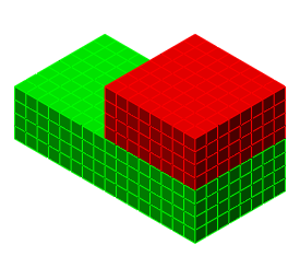
Two part assembly. |
|
|
|
|
|
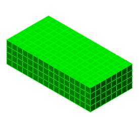
Smaller part hidden (for illustrative purposes). |
|
|
|
|
|
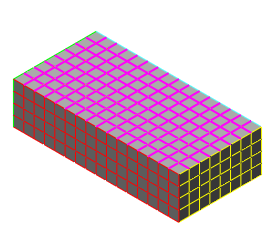
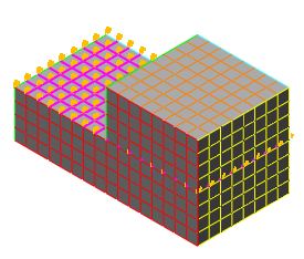
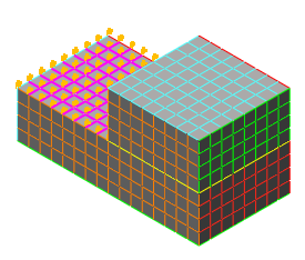
Top surface of large part is selected (magenta color). Note how the top is one big surface without using the splitting. |
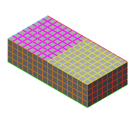
Top surface of large part is selected near the left end (magenta color). Note how the top is split into two portions when using the splitting. |
|
|
|
|
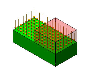
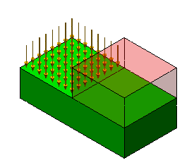
A pressure load is applied to the selected surface on the larger part. It is easy to overlook that the load is applied underneath the smaller block in the model without surface splitting. |
|
|
|
|
|
In the Results environment (with Transparency used on the smaller part), it can be seen that the pressure is applied over the entire face. |
In the Results environment (with Transparency used on the smaller part), it can be seen that the pressure is applied over the intended region. The pressure is not applied under the smaller part. |
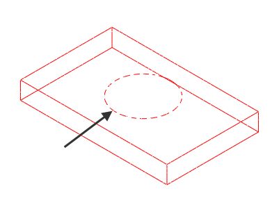
Although some CAD programs have the ability to split a face or surface into smaller regions, surface splitting provides an alternative method of creating a split face. (For those CAD packages that do not provide the ability to split a face, surface splitting in Autodesk Simulation is the only practical method.) Imagine that the part being modeled is welded to a round support piece, and the support piece is not needed in the analysis. However, the pattern of the round support is needed in the mesh of the model to apply the boundary conditions. Using the surface splitting feature, the method of creating this would be as follows:
|
|
A wire frame view of one of the parts in a hypothetical analysis. Boundary conditions are desired on the part around the circular feature (arrowed) on the face. (This is simulating the weld between this part and the support which is not included in the analysis.) Without putting some kind of feature in the CAD solid model, such as splitting the face or adding a fictitious step, the part would import and mesh without having the nodes in the circular pattern. The mesh would be a rectangular pattern on all 6 faces of the solid, and there would only be 6 surfaces on the part. |
|
|
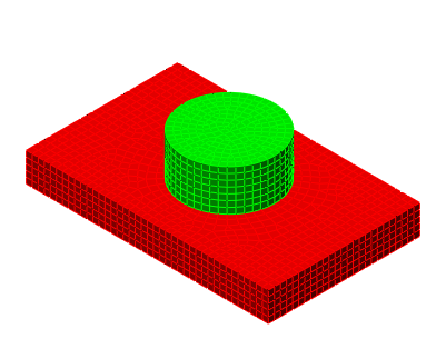
By adding the support to the CAD solid model and importing into Autodesk Simulation, the circular pattern desired for the boundary conditions is created by the mesh matching. |
|
|
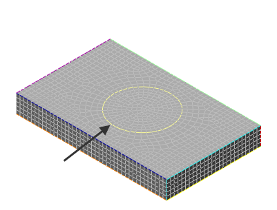
Furthermore, by using the surface splitting during the import, the rectangular face is split into a surface of a rectangle with a hole and a surface of a circle. This also adds new edges to the model (the perimeter of the support in yellow, arrowed) making it very easy to apply the boundary conditions to the edge of the surface. If a pressure were being applied instead of boundary conditions, the circular area can be selected with using the splitting. Since the support is not required in the analysis, it can be deactivated in the FEA Editor. |
When importing a CAD model and the dialog is activated, you have an option to turn surface splitting off permanently: Do not ask this question again. If this prompt is deactivated, it can be re-enabled from the OptionsCAD ImportGlobal CAD Import Options, and choosing the option Ask each time.