The electrostatic brick elements can be 4-node tetrahedral, 5-node pyramids, or 6-node wedges intermingled with the 8-node bricks. Whether these elements act like conductors (resistive material) or dielectrics (insulators) is determined by the electrostatic analysis type selected (electrostatic field strength and voltage or electrostatic current and voltage). Three-dimensional electrostatic elements are used to model devices such as fuses, transmission lines or porcelain insulators.
Parameters of Brick Elements
When using brick elements, in Material Model, specify the material model for this part . If the material properties in all directions are identical, select Isotropic. If the material properties vary along three orthogonal axes or vary with temperature, select Orthotropic. If the material properties will vary with the temperature, select either Temperature-Dependent Isotropic or Temperature-Dependent Orthotropic .
Next, in Integration Order, select the integration order to use for the brick elements in this part. For rectangular shaped elements, select 2nd Order. For moderately distorted elements, select 3rd Order. For extremely distorted elements, select 4th Order . The computation time for element stiffness formulation increases as the third power of the integration order. Consequently, use the lowest integration order which produces acceptable results to reduce processing time.
Orientation of Brick Elements
If this part of brick elements is using an orthotropic material model, in the Element Definition dialog box, Orientation tab, define the orientation of material axes 1, 2 and 3.
- The r axis is defined as the vector from Orientation Node 1 to Orientation Node 2.
- The s axis is perpendicular to the r axis; lies in the plane formed by nodes 1, 2, and 3; and is on the same side of the r vector as Orientation Node 3.
- The t axis is the cross product of the r and s axes.
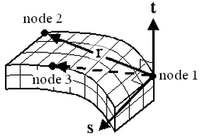
Figure 1: Orientation of the Material Axes
To Use Brick Elements
- Verify that a units system is defined.
- Verify that the model is using an electrostatic analysis type.
- Right-click the Element Type heading for the part that to be brick elements.
- Select Brick.
- Right-click Element Definition, and then click Edit Element Definition.
- In Material Model, select the appropriate material model for this part.
- Click OK.