One FEA model (one .FEM file) can contain numerous analyses or Design Scenarios: the results of each scenario are saved in a separate folder under the main model folder. For example, one model could contain all these analyses:
- Design Scenario 1: Fluid Flow analysis
- Design Scenario 2: Steady State Heat Transfer analysis, using the results from the fluid analysis.
- Design Scenario 3: Static Stress with Linear Material Models, using the results from the heat transfer analysis, with gravity in the X direction and nodal forces on load cases 1, 2, 3.
- Design Scenario 4: Static Stress with Linear Material Models, using the results from the heat transfer analysis, with gravity in the Y direction and nodal forces on load cases 1, 2, 3.
- Design Scenario 5: Static Stress with Linear Material Models, using the results from the heat transfer analysis, with gravity in the Z direction and nodal forces on load cases 1, 2, 3.
The tree view for the above design scenarios is shown in the following image (scenario 5 is active).
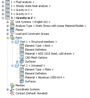
When working with a CAD Solid Model, each Design Scenario uses the same CAD geometry, but all other parameters (mesh size, loads, constraints, manually added elements, and so on) can be changed from one scenario to another.
When working with hand-built models, the model can be completely different in each scenario. For example, the model named Electrode Arm Analysis (file name Electrode Arm Analysis.fem) can consist of individual analyses for several components that make up the arm, such as the stress analysis of the arm in Design Scenario 1, the stress analysis of the clamp in Design Scenario 2, and the thermal analysis of the bus in Design Scenario 3. It's up to you whether these three analyses are in one model with three design scenarios or three different models with one design scenario each.
Work With Design Scenarios
The current Design Scenario is shown in bold in the tree view. To create a new Design Scenario, use any of these techniques:
- Right-click the current Design Scenario and choose New. This creates a new Design Scenario with no mesh, no load, no input, and so on. (If the model includes parts from a CAD solid model, the CAD geometry is included in the new Design Scenario.)
- Right-click the current Design Scenario and choose Copy. This creates a new Design Scenario with the same mesh, loads, input, and so on as the original scenario. Make any changes in the new Design Scenario as needed. Results are not copied to the new scenario. If the results are needed in the new scenario, use Windows Explorer to copy the files (but not the .mod folder) from the original design scenario folder to the new folder. See Setting Up and Performing the Analysis: File Extensions for the structure of a model's folder.
- If you attempt to change the analysis type, you are given the option to copy the existing scenario or to continue working in the existing scenario. (The analysis type can be changed by right-clicking on the Analysis Type branch in the tree view and choosing Set Current Analysis Type, or by using the pull-down menu Analysis
 ChangeType.)
Once the model has multiple Design Scenarios, switching to a different scenario can be done with one of these methods:
- Click the + sign next to the Design Scenario that you want to activate.
- Right-click the Design Scenario that you want to activate and choose Load.
When switching between design scenarios, you is prompted to save any changes in the current scenario. You are essentially closing one model and opening another, so changes normally should be saved. In some cases, the changes made to the current scenario may not be readily apparent to you. Autodesk Simulation may make internal changes. It is always safe to choose Yes to save the current scenario.
To rename a Design Scenario, right-click the name and choose Rename. A Design Scenario can also be renamed by highlighting it and pressing the <F2> key.
To delete a Design Scenario, right-click the name and choose Delete. Alternatively, highlight it and press the <Delete> key. All files in the corresponding Design Scenario folder, including any files that you have created, are deleted. (Technically, the Design Scenario folder is deleted. Anything inside the folder is deleted.) The current Design Scenario cannot be deleted.
You can also right-click a Design Scenario and select to Edit CAD Model, Check Model, or Run Simulation.
Design Scenarios versus Load Cases
Some analysis types (primarily Static Stress with Linear Material Models) have the capability to perform multiple load cases in the same analysis. It gives a different set of results due to different loads on the same model. In the Results environment, the results due to each load case can be viewed sequentially. A similar outcome can be obtained by using different Design Scenarios. When should you use Design Scenarios instead of load cases?
Multiple load cases within one analysis require that a model be analyzed once. Different Design Scenarios require each scenario to be analyzed. Due to the nature of the solution process, the additional time to solve the additional load cases is small compared to the time to perform an additional analysis from scratch. Thus, using load cases is more efficient than using different Design Scenarios. The table below summarizes when to use load cases and when to use Design Scenarios.
- Geometry, mesh, and element input (plate thickness, and so on) are the same.
- Loads can be applied to different load cases, such as
- Nodal forces and moments (assigned to individual load cases when applied)
- Pressures can be scaled by a different factor in each load case
When to use Load Cases
- Geometry, mesh, or element input is different in each situation.
- Loads cannot be changed as required for the analysis by using different load case. For example,
- The gravity vector is constant in one analysis. Use different Design Scenarios to change the gravity vector.
- Distributed loads on beam elements can be scaled in different load cases, but individual distributed loads cannot be changed. Use different Design Scenarios.
- Different analysis type in each situation.
When to Use Design Scenarios