- On the Quick Access Toolbar (QAT), click the
 Save icon.
 - Click
 Tools
Tools  Edit CAD with Fusion. The solid model opens in Inventor Fusion.
 - If the Welcome to Inventor Fusion dialog box appears, click the Close button to dismiss it.
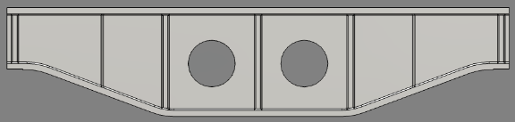
- Click near the middle of the Front face of the ViewCube. The front view is displayed as shown below.
There are two methods to increase the beam height by 60 mm while keeping the web holes centered vertically:
- Raise the top flange 60 mm and raise the location of the holes 30 mm.
- Raise the top flange 30 mm and lower the bottom flange 30 mm.
We will use the latter method.
- Click and drag to draw a selection window that encloses only the top flange and all of the corner chamfers on the underside of it, as shown below.
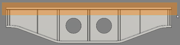
The top flange andchamfers will become highlighted in blue.
- Click
 Home Solid Move. A move triad will appear on the screen. It may or may not be oriented as needed, specifically with a vertically upward axis. If not, perform the optional steps under A below. Otherwise, skip to step B.
 - Click the
 Reorient Triad icon that appears near the Move Triad.
 - Point to one of the vertical edges of the beam (for example, one of the rib edges), and click while a triad with a vertical axis (preferably an upward one) is appearing.
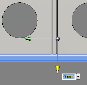
- Click the Finish Reorient button. The triad should look similar to the image below.
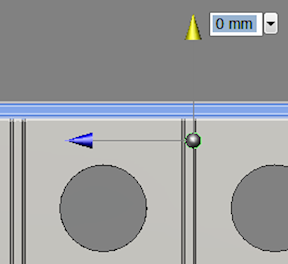
- Notice in the above image that the dimension input field for the vertical move axis (yellow) is already selected. If it is not, click the yellow arrowhead to activate the vertical move dimension field. If your vertical move axis is pointing downward instead of upward, substitute a negative dimension in the next step to move the flange upward.
- Type 30 and press Enter to lock in the vertical move distance.
- Press Enter again to complete the Move operation and exit the command.
- Click the
- Click and drag to draw a selection window that encloses only the bottom flange and all of the corner chamfers on the upperside of it, as shown below. Be careful to NOT fully enclose the web holes.
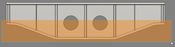
The bottom flange and chamfers will become highlighted in blue.
- Click Home Solid Move. A move triad will appear on the screen. It may or may not be oriented as needed, specifically with a vertically downward axis. If not, perform the optional steps under A below. Otherwise, skip to step B.
- Click the Reorient Triad icon that appears near the Move Triad.
- Point to one of the vertical edges of the beam (for example, one of the vertical rib or rib chamfer edges), and click while a triad with a vertical axis (preferably a downward one) is appearing.
- Click the Finish Reorient button. The triad should look similar to the image below.
- Notice in the above image that the dimension input field for the vertical move axis (yellow) is already selected. If it is not, click the yellow arrowhead to activate the vertical move dimension field. If your vertical move axis is pointing upward instead of downward, substitute a negative dimension in the next step to move the flange downward.
- Type 30 and press Enter to lock in the vertical move distance.
- Press Enter again to complete the Move operation and exit the command.
- Click the
- Click the
 Home icon above and to the left of the view cube for an isometric view of the model.
Note: We have increased the height of the support beam, at mid-span, from 350 mm to 410 mm using the Move command. Many other modifications are possible, such as:
- Push on an edge to turn it into a fillet.
- Push or pull on existing fillets to change the radius.
- Push or pull on individual surfaces to change the thickness or shape of a structure or the diameter of a hole.
- Bend and move edges.
- Add or remove features (such as holes).
- Mirror features, create rectangular or polar patterns of features, or create a pattern of features along a specified path.
- Split surfaces, which is useful in FEA models to restrict surface loads to a portion of a larger surface.
Please consult the Fusion Help for additional information.
Before returning to Autodesk Simulation, save the revised support beam as an Inventor Fusion file.
- On the Quick Access Toolbar (QAT), click the Save icon. The original CAD solid model will not be overwritten because it is a Step file (.stp extension), whereas Fusion files have a .dwg extension.
- Navigate to the folder where the original support beam Step and FEA model files reside.
- Accept the default filename of Support Beam.dwg and click the Save button.
- Click
 Home Simulation Simulation Mechanical or Simulation Mechanical 360 (depending upon your Autodesk Simulation product).
 - Click No when asked if you want incoming CAD material data to replace the existing material properties in Autodesk Simulation.
- After the model is transferred, it will be automatically remeshed using the parameters specified for the original analysis.